West End Workbench
Moderators: 52D, Tom F, Rlangham, Atlantic 3279, Blink Bonny, Saint Johnstoun, richard
-
- LNER A4 4-6-2 'Streak'
- Posts: 4303
- Joined: Wed Oct 25, 2006 8:46 am
Re: West End Workbench
Some of you may have seen a diversion into building foreign wagons on RMWeb. Today I came back to some more familiar subjects.
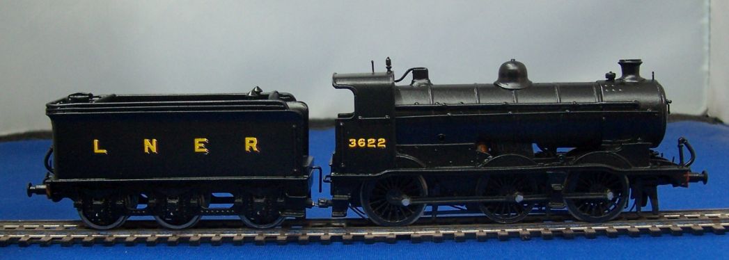
I found time to letter up the J6; after some successful test running on Grantham, this is slated for the Newcastle show.
I also picked up one of the wagons I acquired from a deceased collection earlier in the year. A couple of them were used as 'have a go' pieces at Thirsk Show while I was demonstrating weathering. They've since been through the paint stripper and onto the corner of the bench. I picked this one up to have a go at detailing it today.
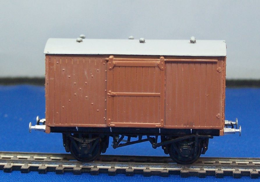
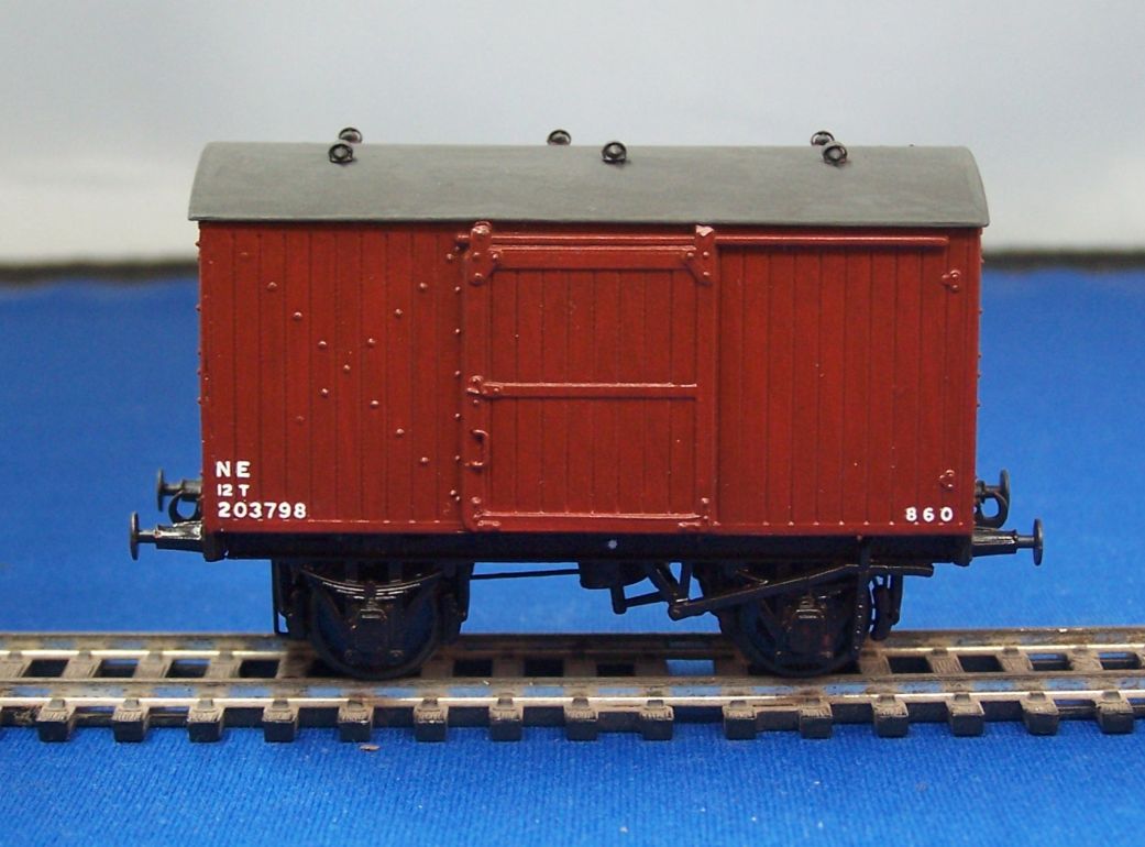
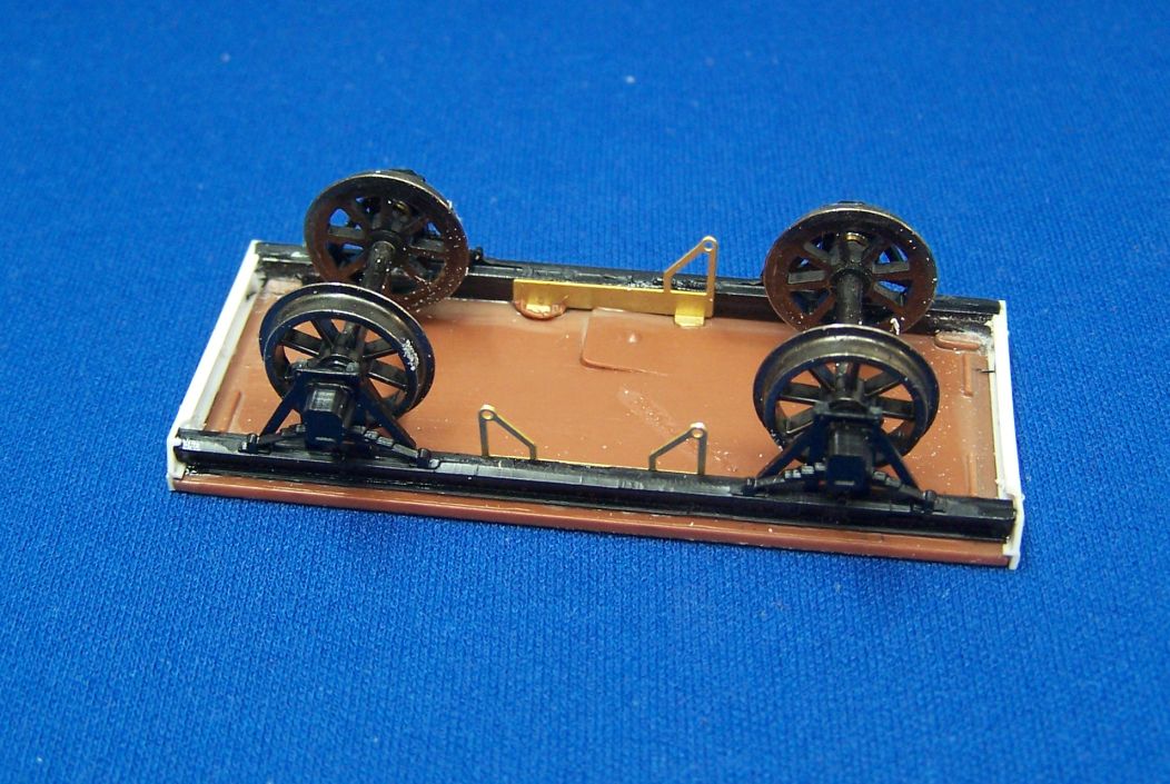
It was only when I had it in my hands and upside down today that I realised that it wasn't quite the Parkside Fruit van I'd taken it for. The builder has used the ends from a Fruit van kit but the sides from the standard van and a steel underframe to make the later diagram Fruit van. I haven't had it beside Tatlow to see just how accurate it is, but it's a good idea. Someone does the 'Fruit' plates as an etch, I'm sure, I just have to remember who it is.
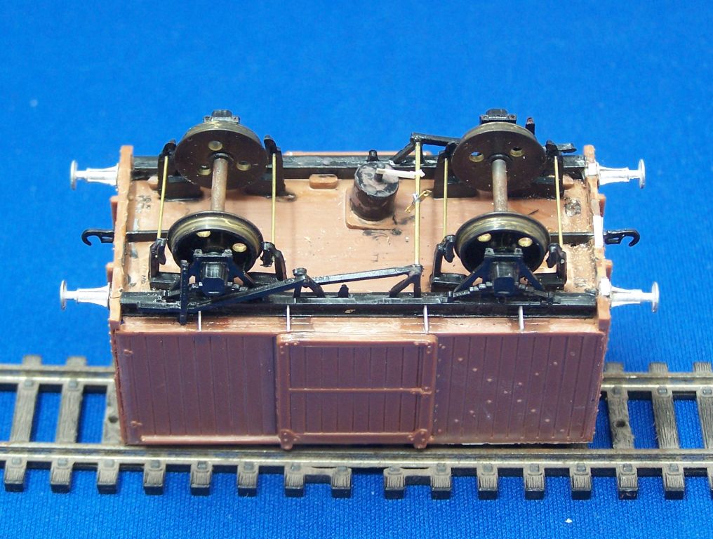
It's had my usual additions to the underframe, replacement buffers and couplings. There's still a little more to add, then a weight, better roof vents and off it goes for paint.
This was the main focus of the day, though - a job I started a couple of weeks ago.
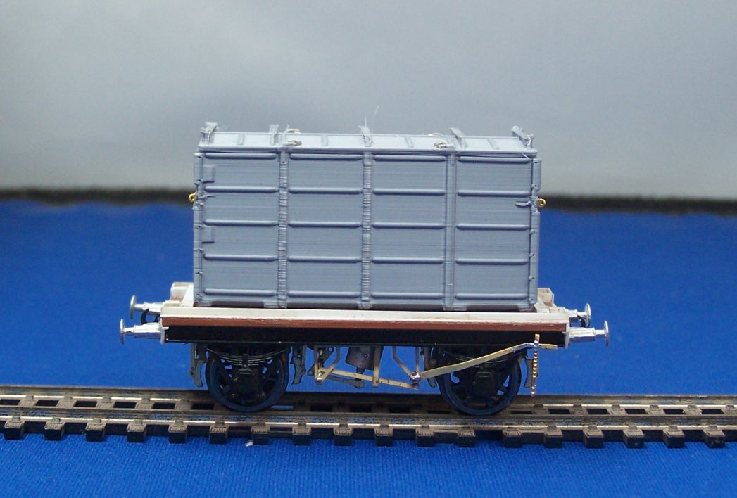
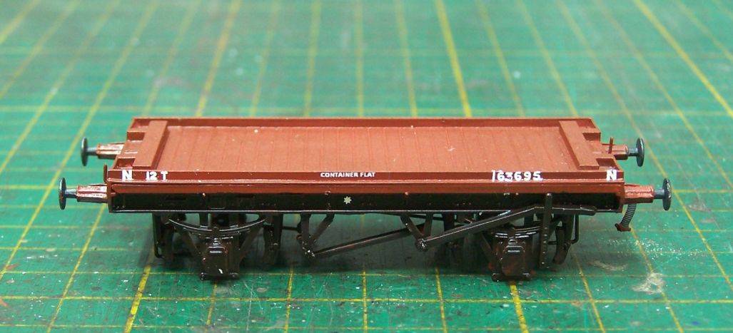
Earlier in the year, Carlislecitadel of this parish kindly sent me some printed containers, including a couple of the pressed steel ones I've been keen to get hold of for Grantham ever since we started selecting stock for it. I've not really done much with them up to now, but I do want them on the Scotch Goods for Newcastle. I looked at my available options for conflats and found a couple of Conflat S kits and some resin cast Conflat Vs from Mr. King. At the time these were photographed on the Scotch Goods, around the time the V2s started hauling it, the diagram 76 container flat seems to have been the most common type.
I was flicking through Tatlow looking at the different combinations and designs when it occurred to me that a D76 was not very far from Parkside's PA06 underframe kit. I had a few of these under the bench, so I pitched into one and set about building it.
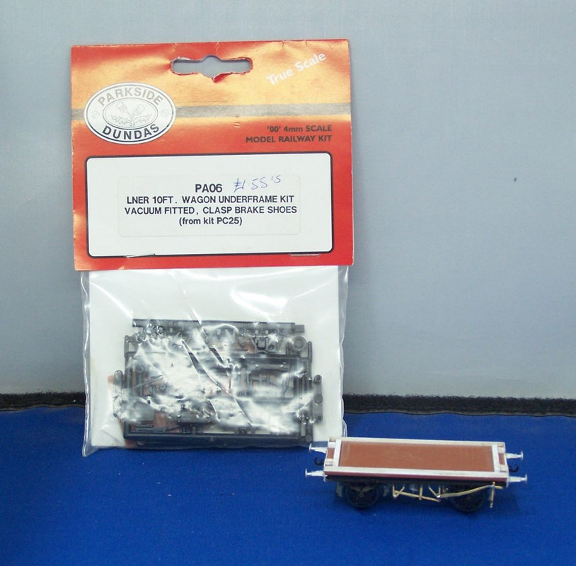
In the end I only used the floor and solebars, but I chose to discard the brake gear and use brass instead. Buffer beams from Evergreen channel, buffers LMS, the rest the Mainly Trains LNER fitted brake gear etch and bits of wire.
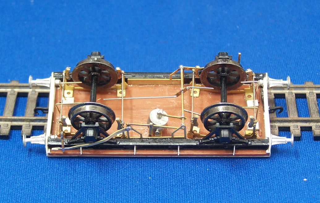
The Parkside floor is over thickness, but I can live with that as a compromise as it gives a solid, square basis for the rest of the wagon.
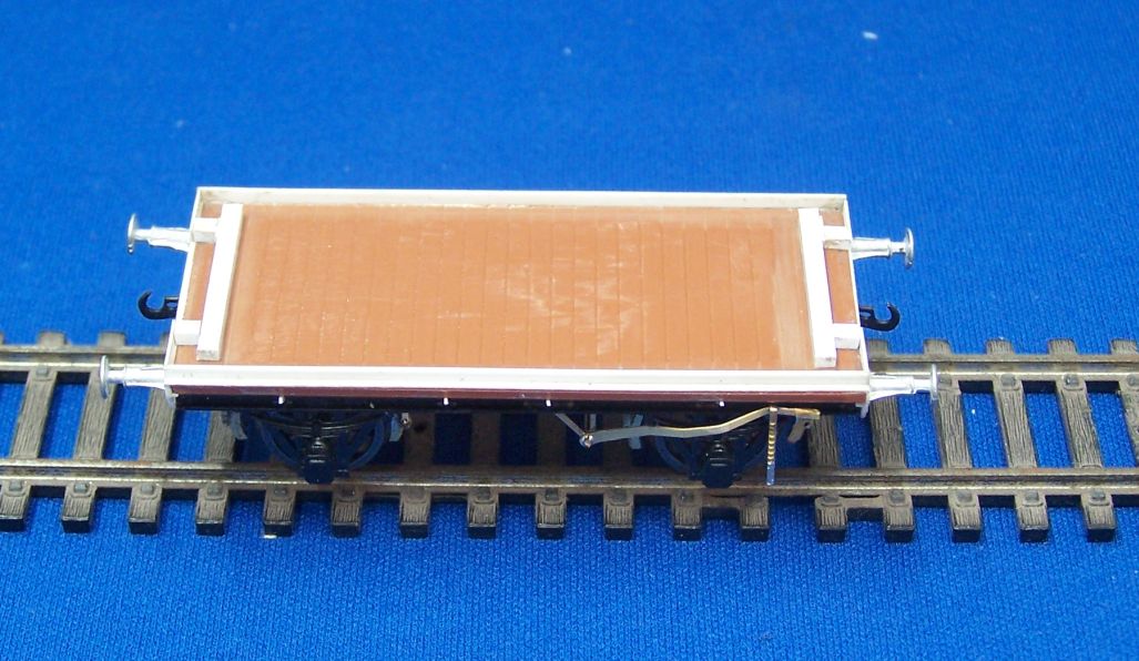
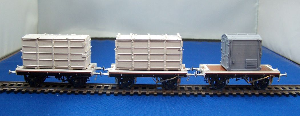
The top is fairly simple - lengths of Evergreen strip following the arrangement shown in Tatlow 4A p 209. I haven't bothered with the bits under the container. The container itself has had brass eyes from Roxey added and the top tidied. The lifting loop brackets had printed quite misshapenly and with fine filaments hanging off which were very resistent to cleaning up. After I'd broken two off, I waved the white flag, broke the other off to match and just glued wire loops to the roof to look like the lifting shackles. There's still the odd detail to add but it's largely there and looks the part to me. I've started another so I'll go into more detail on that as I make progress.
-
- GNR C1 4-4-2
- Posts: 713
- Joined: Tue Nov 27, 2012 8:59 am
- Location: South Australia
Re: West End Workbench
Sorry to say this Jonathan but the brake gear is the wrong way around. The operating rod on the side connecting two V hangers is angled the wrong way and shouldn't the vacuum cylinder be on the other side?
Andrew
Andrew
-
- LNER A4 4-6-2 'Streak'
- Posts: 4303
- Joined: Wed Oct 25, 2006 8:46 am
Re: West End Workbench
Morning Andrew,
It felt off as I was putting it together and I couldn't put my finger on why. It's not changing now, it's too firmly stuck. I might be able to move the vac cylinder without causing too much damage.
Better make sure I get the next one right.
It felt off as I was putting it together and I couldn't put my finger on why. It's not changing now, it's too firmly stuck. I might be able to move the vac cylinder without causing too much damage.
Better make sure I get the next one right.
-
- LNER A4 4-6-2 'Streak'
- Posts: 1728
- Joined: Fri Dec 23, 2011 3:34 pm
Re: West End Workbench
The body OK, but the most exotic underframe ever: steel channel solebars, timber bufferbeams. Easy enough to correct for a side on view. (I have seen this before in cross kitted variants of LNER vehicles, choice of kit parts was limited back in the 1970s...)jwealleans wrote: ↑Sun Sep 03, 2023 9:01 pm
It was only when I had it in my hands and upside down today that I realised that it wasn't quite the Parkside Fruit van I'd taken it for. The builder has used the ends from a Fruit van kit but the sides from the standard van and a steel underframe to make the later diagram Fruit van. I haven't had it beside Tatlow to see just how accurate it is, but it's a good idea...
-
- LNER A4 4-6-2 'Streak'
- Posts: 4303
- Joined: Wed Oct 25, 2006 8:46 am
Re: West End Workbench
Given that it's all painted black, filing/paring the buffer beam ends almost flat should give the illusion. I'll see how motivated I feel.
-
- LNER A4 4-6-2 'Streak'
- Posts: 4303
- Joined: Wed Oct 25, 2006 8:46 am
Re: West End Workbench
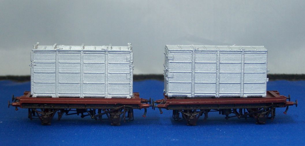
I have assembled two more D76 conflats, so here is a step by step for those who might fancy a go.
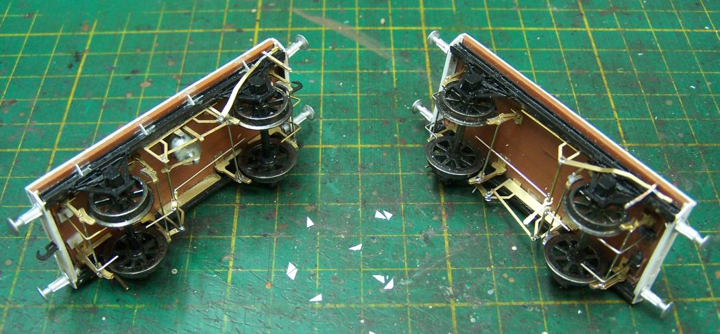
From the PA06 packet we only need the floor and solebars to start with. As I always tell people when demonstrating plastic wagon building, fit one solebar to the floor and leave it overnight to harden. That way you have a fixed point to work against when you fit the second one and the wheels and can check the axles are square.
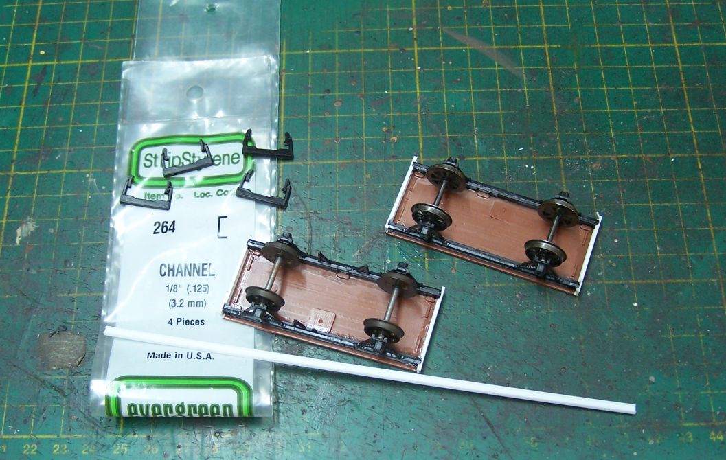
The buffer beams are Evergreen 264, their 1/8" channel. I also use this for solebars on scratchbuilt wagons and coaches, it's a very useful item. You'll need to cut the lip away to allow it to sit tight up to the solebar and there will be a small amount projecting out past the end of the floor. Don't worry about this for now.
This is usually all you need out of the PA06 pack, but knowing that not everyone solders, I decided to build one of these using the PD brake gear. The other was done with my usual Mainly Trains MT225 LNER fitted brake gear etch. For the plastic gear, I've taken the four sets of shoes off the sprue and drilled them 0.5mm just behind the middle of the shoe.
For the one with the brass brake gear, you need to remove the V hangers from the solebars and attach the brass ones from the etch. These are superglued. For those (like me) who can't remember, the double V hanger goes on the side opposite the cylinder.
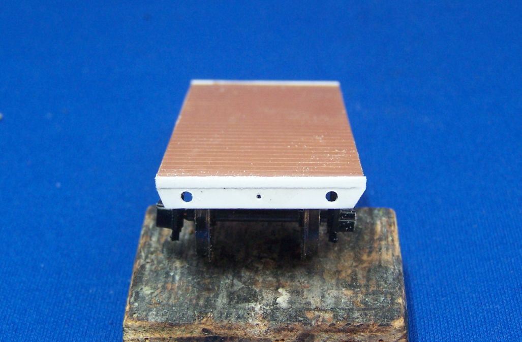
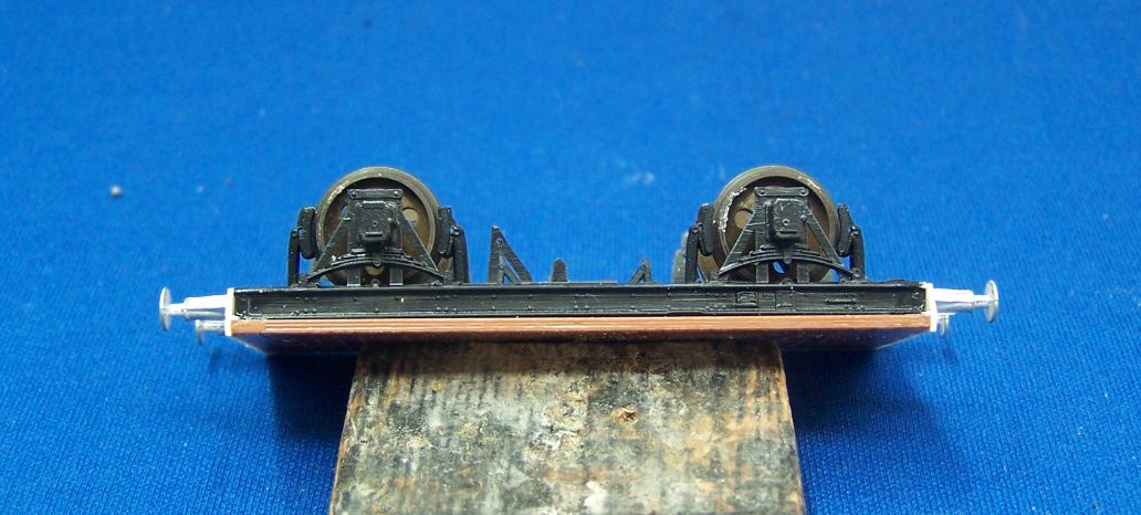
Irrespective of brake gear, we need to finish the ends. The buffer beam ends slope in to the solebar, so cut them using floor and solebar as guides. This one is slightly unequal - it's not a massive issue but some light filing will deal with it if it upsets you. Find the centre (I use dividers) and make a guide hole for the coupling, then use that to space the buffer holes each side. I drill these fairly small then use a small round file rotated between my fingers to enlarge the holes. A 2mm drill will shred the bufferbeam. Ask me how I know this.
I've also stuck a strip of Evergreen along the top of the bufferbeam to bring the floor out flush. This might be 10x40 or 20x40, there's some variation in the Parkside mouldings. Once this has hardened, file the front flush so there are no steps.
Buffers are LMS B004. I had to wait for some more of these this week as well, but Dave Franks is faster than his own shadow so it didn't delay anything. the slot for the coupling hook is opened up with a very small file. You can also see here where I've drilled the Parkside brake shoes and the V hangers to thread .45 wire through them later on.
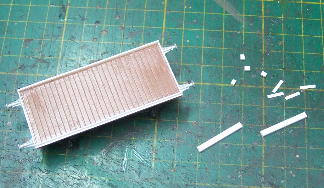
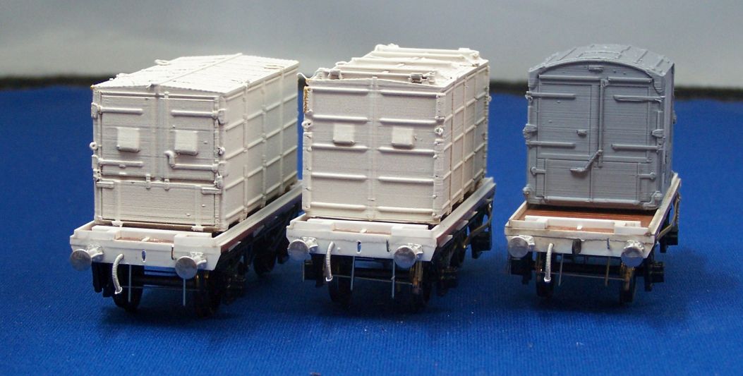
I did the deck next. Start with a piece of 10x30 Evergreen along the long edges. Once this is stuck, a piece of 20x60 on edge makes the quite distinctive angle along the side. It's probably overscale, but it needs to be able to take the container fixings and also have room for the lettering. Leave this to harden. Once it's solid, the visible decking picees can be added. As two of these will be carrying B type containers I only did the very end fittings. I didn't have a drawing for these, I just worked out what I thought the dimensions were from the photograph in Tatlow 4A. The thin end plates are 10x40 Evergreen 8mm long, the long cross pieces are 60x80 24mm long and the short intermediate pieces are also 60x80 2mm long, but turned through 90 degrees. Later I added the small L shaped fixing brackets for the large cross piece from 10x30 strip - you can see them in the last photographs below.
Once you've stuck that lot on you're ready to go underneath. If you want one of these for an A type then you can carry on along the floor and use the photograph referenced above as a guide.
How much detail you add underneath is up to you. First, the one made using the Parkside components:
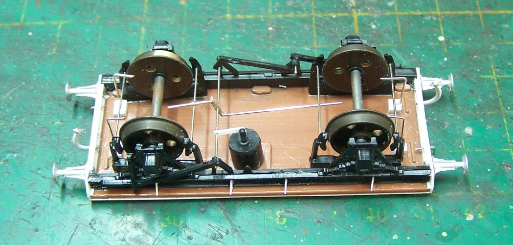
I use .45 wire as the parts will fall apart if you drill larger holes. You also have to be careful attaching the pull rods - I fitted the central piece off the wagon so as not to melt the V hangers and was very quick with the iron fitting the rods.
If you use the brass gear then you just work your way through it and you can use a more accurate thickness of wire for the cross shaft. I add the outside safety loops but not the inside (and I've missed the one on the brake lever linkage on the right hand wagon below) and I don't usually bother with the stay to the axleguard from the brake lever either. The safety loops on the ends are secured into extra lumps of plastic, just offcuts usually. I melt them in with a soldering iron, but you can dril and glue just as easily.
Body fixing brackets are quite visible, though, so I add those. These are 10x80 Evergreen cut to the depth of the solebar behind the wagon edge (about 3mm in this case) then cut in half diagonally. Make one more pair than you need and use the best of them. The one above the brake lever is smaller than the others and they're also slightly truncated at the wagon edge, so don't worry if they stick out slightly, just cut or file them off when set. You'll also need to take out a notch in the top corner to clear the solebar top.
Pretty much ready for paint now - I've added the dangly vac pipe and lamp iron on the end (all fitted LNER wagons had at least one lamp iron on each end). The containers have had a couple of coats of filler primer and then white in preparation for a coat of silver. The A type is also by Sacha.
I hope that's been useful. Any questions?
Re: West End Workbench
What is the "A" Type ?, nothing obvious in Tatlow. Perhaps its LMS ? .
- Dave
- LNER A4 4-6-2 'Streak'
- Posts: 1733
- Joined: Sat Nov 13, 2010 9:33 pm
- Location: Centre of the known universe York
Re: West End Workbench
Flats and containers looking good.
I still have mine to finish, they are being worked on slowly in the background.
-
- LNER A4 4-6-2 'Streak'
- Posts: 1728
- Joined: Fri Dec 23, 2011 3:34 pm
Re: West End Workbench
Oh, that one!!
-
- LNER A4 4-6-2 'Streak'
- Posts: 4303
- Joined: Wed Oct 25, 2006 8:46 am
Re: West End Workbench
Moved the wagons along over the weekend. Fruit van is now painted and lettered. Hopefully the subterfuge with the buffer beam works at normal viewing distances. I'll get hold of a plate for the door whenever I see Ambis at a show.
I also started to letter the D76, but soon realised that the transfers I'd had speculatively printed some time ago were nowhere near correct.
I've spent some time making up a new sheet and I'll get that off to John Peck very soon. The other two and the containers are painted.
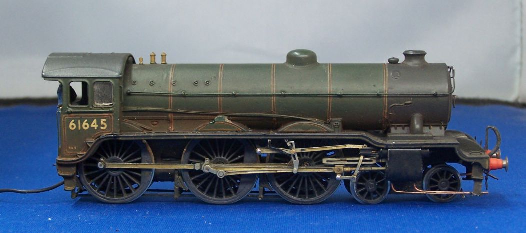
Finally, a bit of nostalgia. 61645 was one of the first locos I built, in around 2004/5. We wanted a decent B17 for Thurston, so we concocted this one from a Hornby body, Comet frames and valve gear and a Dave Alexander tender. It had to be the subclass with the high vac cyiinder on the tender rear and we went for a regiment rather than a stately pile, just to be different. It was the first time I'd erected valve gear. I put it together then Graham Varley made it work properly and it's run round on club layouts ever since. I noticed in May that it was looking a bit tired, so I brought it away to touch up. Jamie observed that it was nose heavy, so I had a go at doing something about that too.
I did have the missing nameplate but it's evaporated from my toolbox, so there's another set on the way. I still have the regimental badges from the first set I fitted as they were not present by the 1950s. I've replaced a missing smokebox handle, touched in paint here and there and also rerouted the wires to the motor so all the space between the rear axles is now full of lead. It's quite heavy. I'm due down in Ely in a couple of weeks for a stock fettling session, so I'll have it ready for trials by then.
-
- LNER A4 4-6-2 'Streak'
- Posts: 4303
- Joined: Wed Oct 25, 2006 8:46 am
Re: West End Workbench
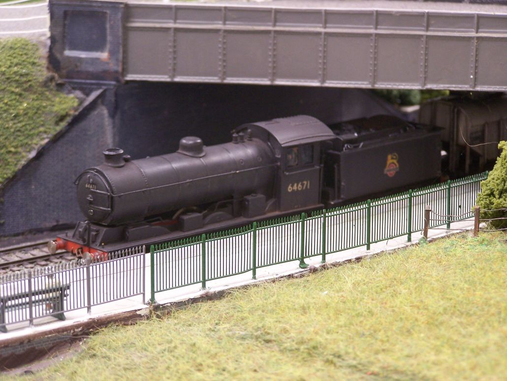
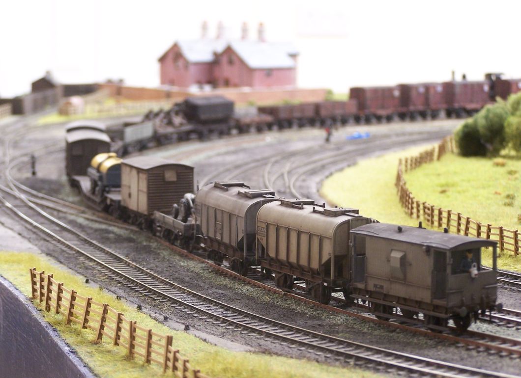
As mentioned above, I was down to Ely this weekend for a running and fettling session on Wickham Market. As it turned out there was a lot more running than fettling, although quite a bit of work was done on the branch set and sidings to get those into good order. I didn't have masses of time for photographs, but I did manage some later in the day when we were mainly running freight. It was good to bring a lot of this stock out which has largely only run twice since we retired Thurston in 2015.
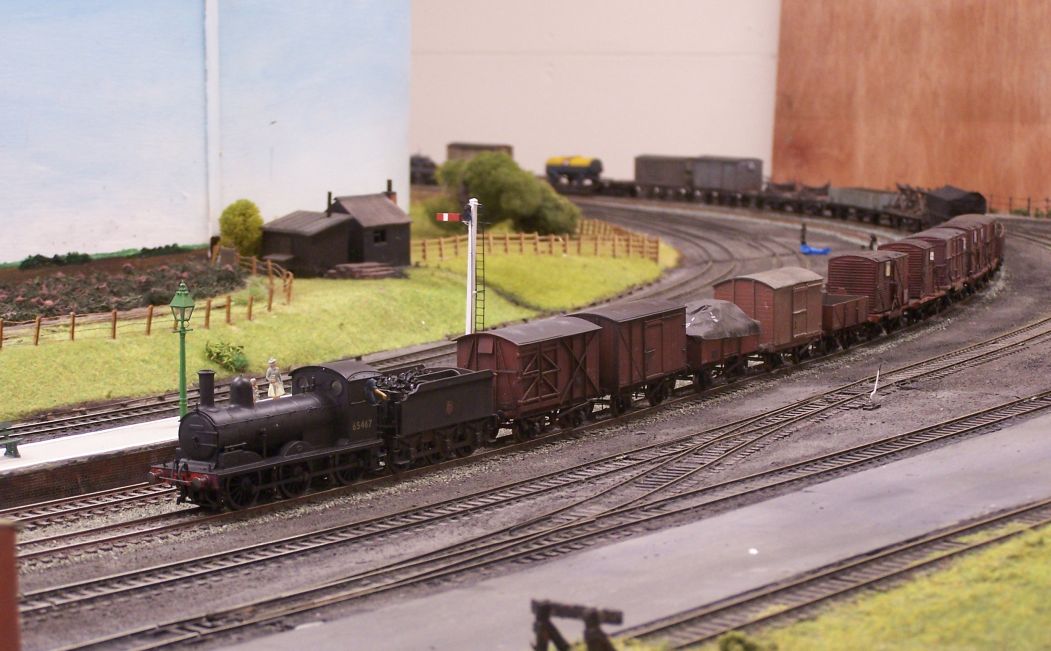
64671 is from a Crownline kit. It's being hinted that I should provide a J20 as well.
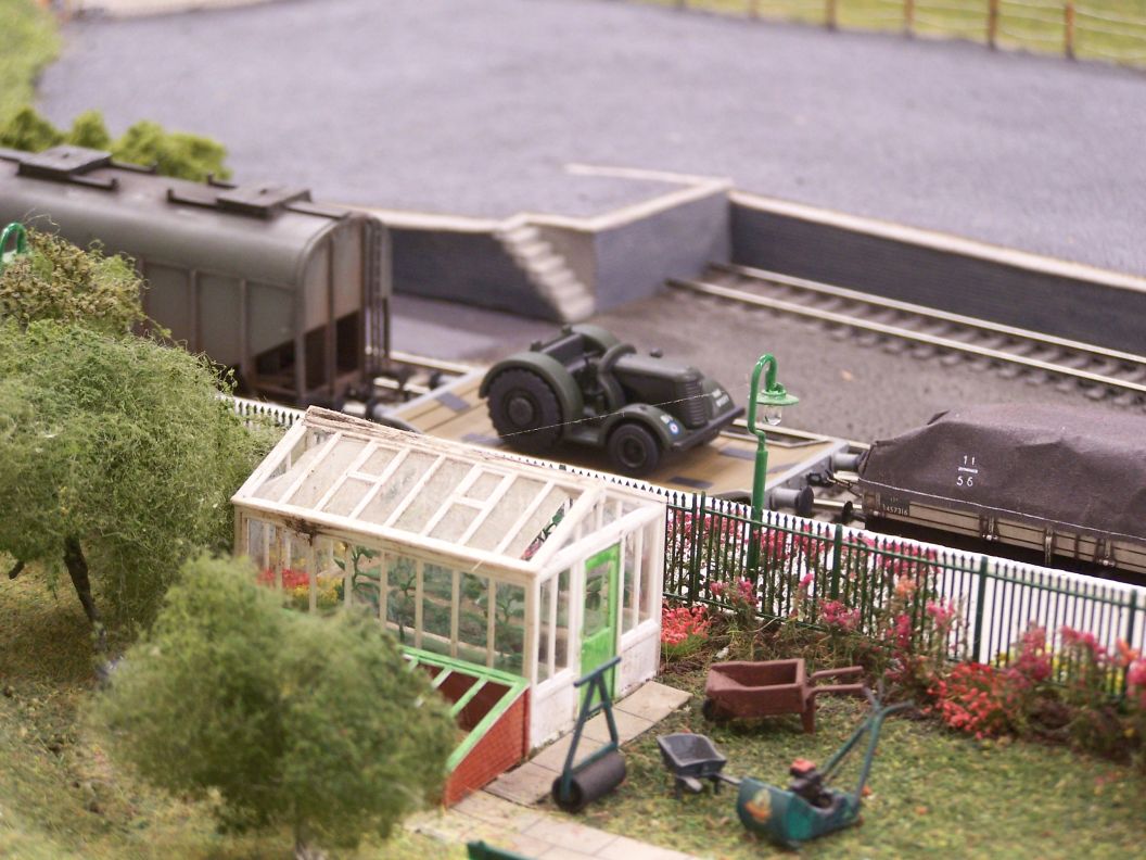
The Hymac by 247 Developments which some readers may have seen on RMWeb. I was quite taken with the details in the garden as well, having acquired a Suffolk Colt with the house I now live in.
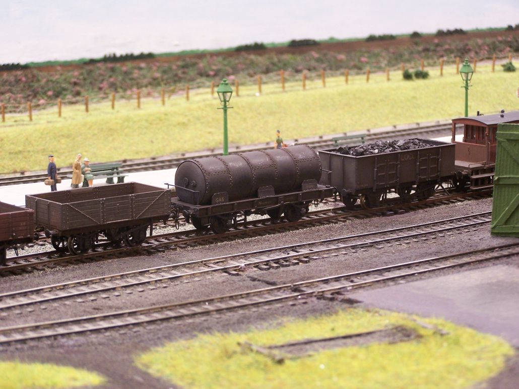
I think I've mentioned it before, but this lovely scratchbuilt gas tank was in a job lot of wagons I acquired from 53A Models a few years ago.
65388, from a Gibson kit, was the first loco I built for Thurston in about 2003. The Palvan behind is a detailed Ks kit.
Parkside trestle wagon, Chivers LMS Tube, ABS twin bolster, Ks unfitted van, D & S GE van, then the warwell with bowser which featured on here recently.
Towards the rear, Hornby brake van, Bachmann grano, then an Acorn grain hopper which has the distinction of being the worst brass kit I have ever built.
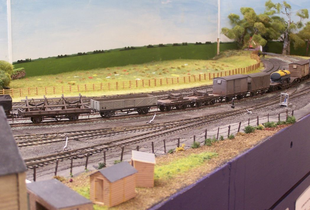
Thurston used to feature a lengthy lie-by across the front in which we would park an Engineers' train or the weedkilling train so the public could get a good look at them. There's no such feature on WM, but there is a road at the back of the up platform which we thought might lend itself to parking a train up.
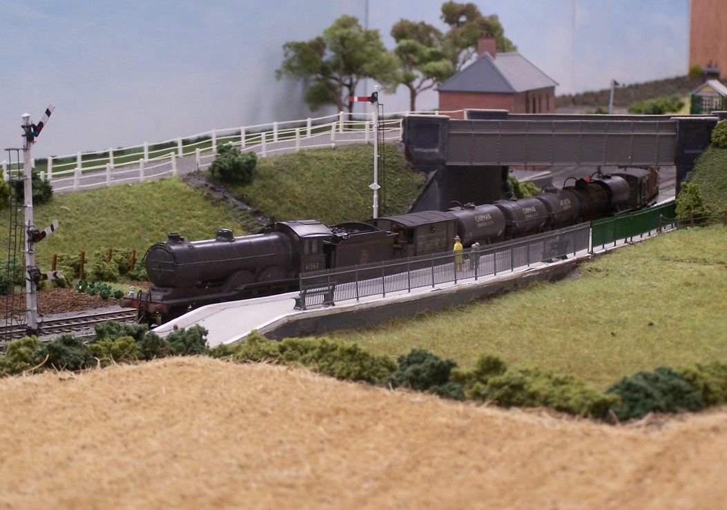
61562, the Coopercraft B12, was the usual motive power for this; here the driver has brought it to a halt at the starter, eased past until clear and then started to set back once the road was set.
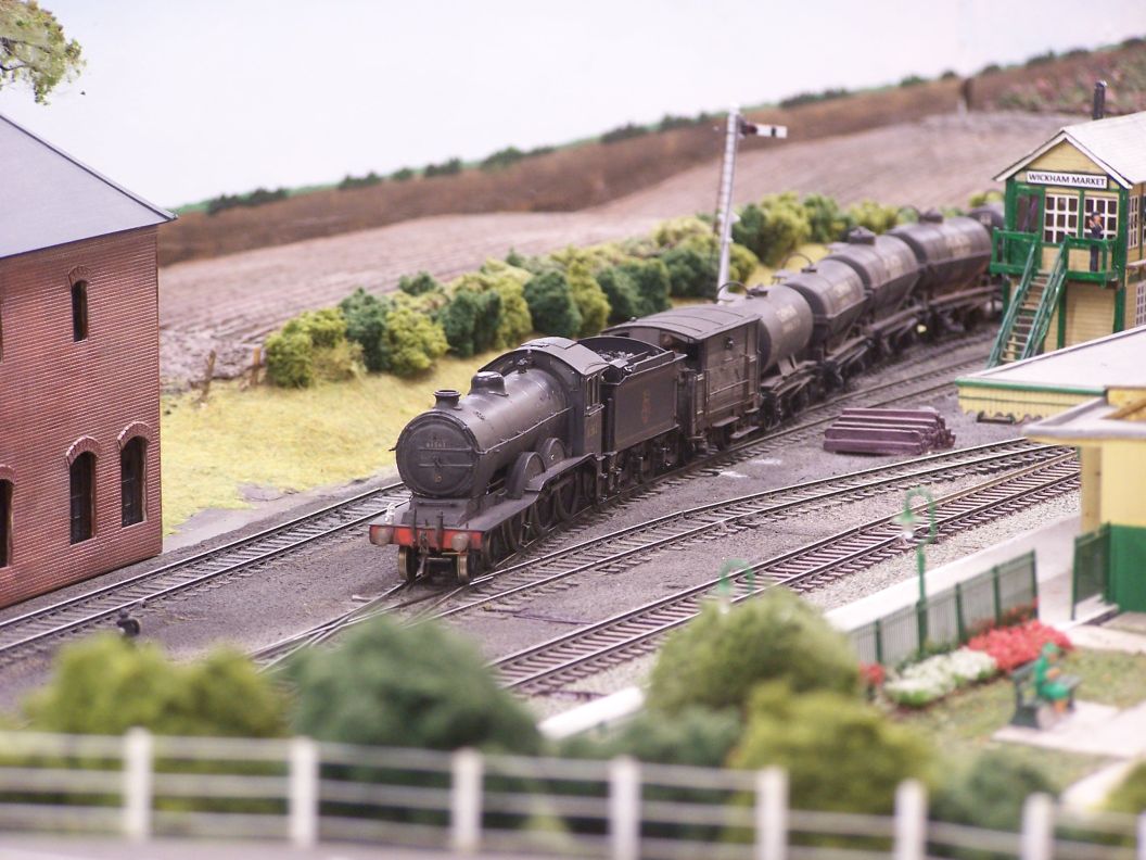
The train is now clear of both main lines and passing behind the signal box and into the back road proper. It accomplished this successfully. The other place the weedkiller might well be sent is up the Framlingham branch (both the Dr Ian Allan photographs I have of it were taken along that line). The loco objected to the qute sharp curve into the branch sidings, however, so it will probably require different haulage for that working.
For anyone interested in seeing more, Andy Wilkinson kindly allowed me to post his videos from the day onto my YouTube channel.
-
- LNER A4 4-6-2 'Streak'
- Posts: 4303
- Joined: Wed Oct 25, 2006 8:46 am
Re: West End Workbench
Last week, having some time between applications of paint and transfers on different models, I made a start on another 3D printed wagon. I'd been pointed in the direction of https://bygone-wagons.com/ before, but had only seen GWR prototypes on there and nothing which immediately grabbed my attention. I was then advised to look at the 'Upcoming Wagons' page as there was a planned LNER build refrigerated van. The website is behind, in fact, as this kit is available now. I have one of these on Grantham which was made up from some Jim McGeown etches shot down, but another couldn't hurt, so I made contact.
Amanda was very easy to deal with; she's happy to supply wagons built up or in component form and she's not precious about her parts being replaced with those other suppliers. I ordered a couple of the refrigerated vans and also one of the Dyson wagons and tankers on page 2 for another project.
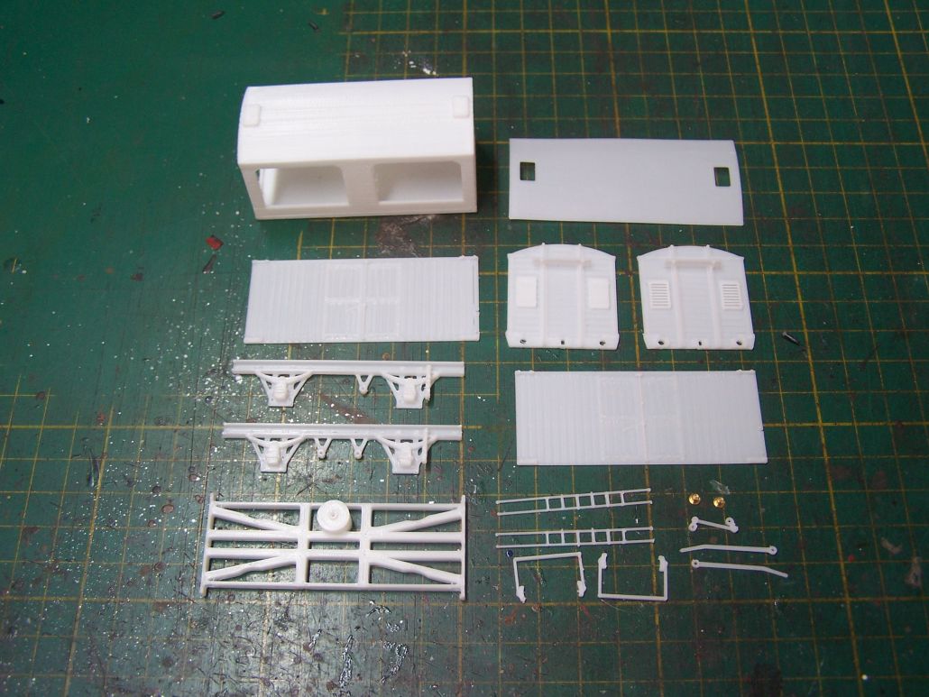
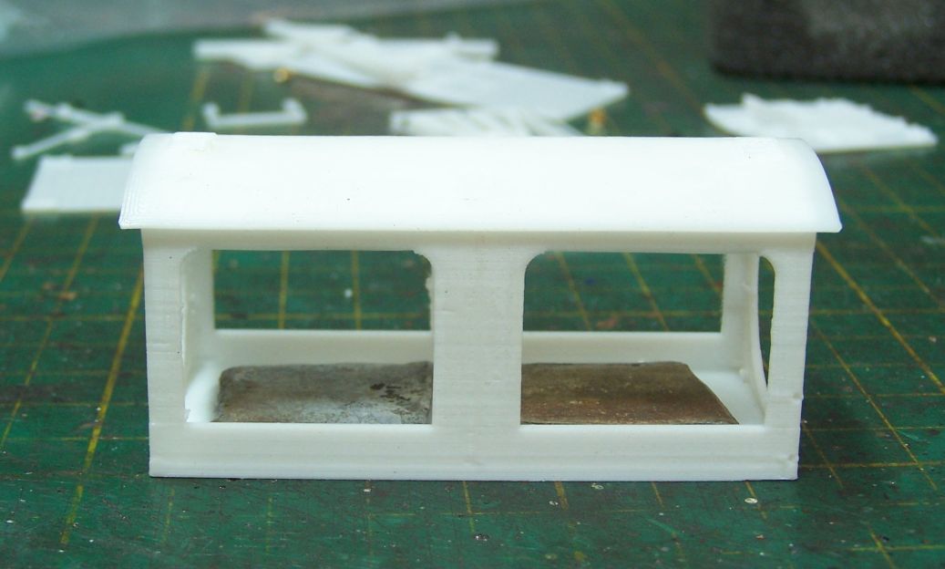
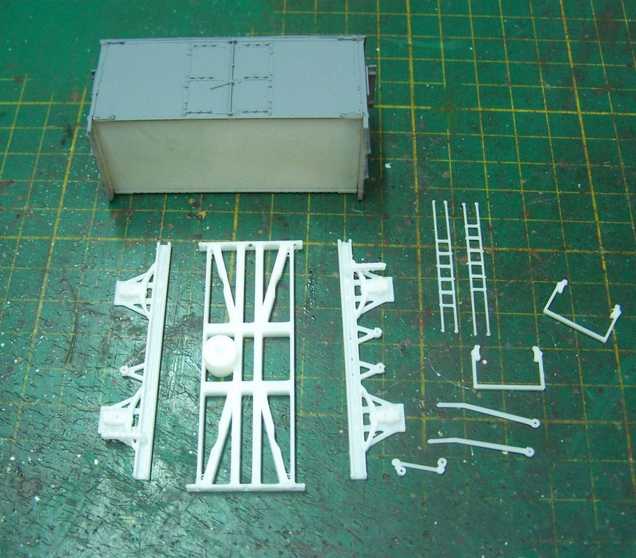
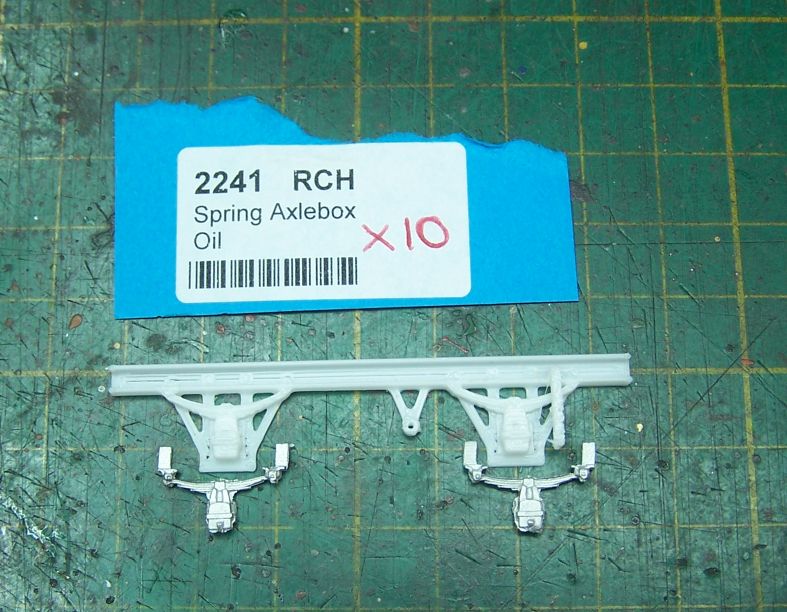
The kit is designed quite differently from others I've put together; there's a basic carcass, top left, to which you then add roof, sides and ends. There's then an underframe piece , solebars, brake gear and ladders to add. Bearings are provided - nice touch, not everyone does that - but not wheels except by special request and EM only.
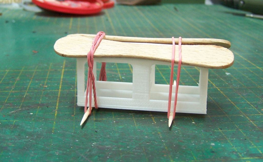
Having test fitted a few of the components, I decided the best order of assembly would be roof - sides - ends. The roof had what amounted to locating holes where the ice hatches are, so it could be fitted in exactly the right place. The sides will then butt up to the roof and are exactly the same length as the carcass, so they can be placed exactly. The ends then overlap the sides and seal the box. I glued the roof with epoxy instead of superglue so I had a bit of time to adjust it and made sure it sat down properly onto the curve of the former. There are print striations on the roof, but my paint/talc roof mix will disguise those. You can make a new piece with 20 thou plasticard if it offends.
The roof having set, I stuck a lump of lead inside while I could still get in.
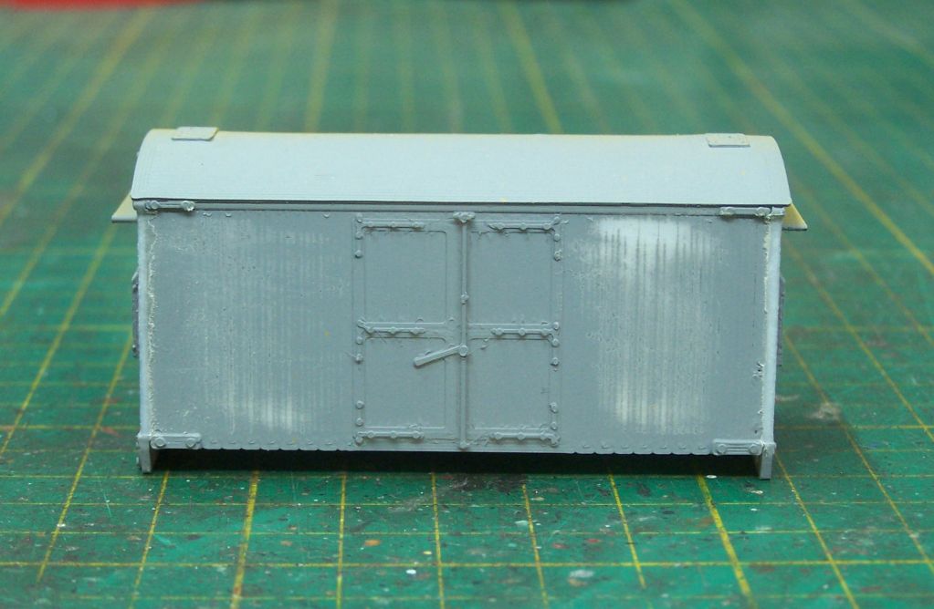
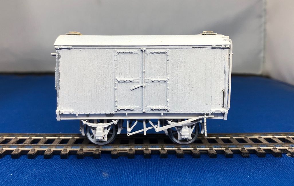
We've jumped a couple of steps here so sides and ends are on. The sides were too wide and so the corner posts were proud of the sides. I've primed it so you can see where I had to file them back to make the whole side flush. You can also see that the bolt heads on the strapping are overscale and there are threads of resin between them which it's worth taking the time to remove. I think those overscale bolt heads are my major criticism of this design and they're not too obvious at normal viewing distances.
At this point I had to assess how I was going to complete the van. Above are the underframe components, at least some of which I planned to replace with brass parts. 3D printed resin simply isn't robust enough for the rough and tumble of exhibition use. Looking at the design of what has been supplied here and given that I'm not doing any sort of formal review for the manufacturer, I decided to discard everything and make a new underframe.
The main part of the underframe assembly which gave me pause were the solebars. In the end I decided not to use them for two reasons. One was that by omitting the main underframe piece, which fits behind and reinforces the buffer beam at each end, I would have a gap at each end. The other was the printed axleboxes which looked a bit vertically stretched to me. Here they are against the MJT parts I eventually used and you can judge for yourself. I made new solebars from Evergreen 1/8" channel.
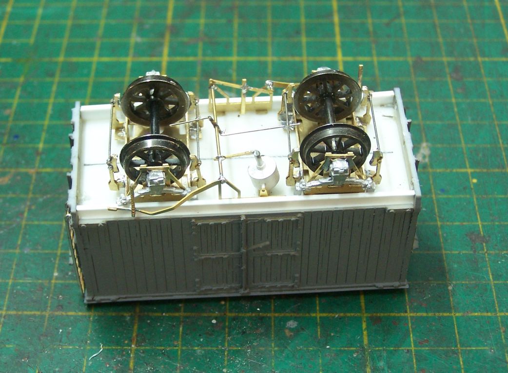
Wheelsets first; MJT axleguards. The fixed one was positioned and checked for squareness then left to set and the Brassmasters jig used to set the other in place.
Solebars and brake gear now fitted. Brake gear is the usual Mainly Trains etch.
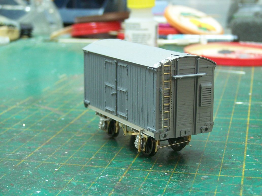
The end ladders are Wizard Models signal ladders with their .45 square rodding added to beef them up and make them look more realistic. Note that I'm not fitting the (LMS) buffers until it's painted as it'll be easier to cut the black buffer beam in with the buffers off.
This is more or less where we are now; side and ice hatch handles added and I've since painted the roof grey.
-
- GNR C1 4-4-2
- Posts: 713
- Joined: Tue Nov 27, 2012 8:59 am
- Location: South Australia
Re: West End Workbench
Hi Jonathan
Extract from my thread Woodcock's Workbench from 4 May.
'I've been distracted with building more wagons, firstly because I wanted to have an express goods on the high level LMS part of my layout to run behind my Claughton 6004 and also similarly I wanted to put together a perishables train for my Bachmann V2 - not that I really needed more wagons for that train but it did see me commissioning a 3D printed LNER refrigerator van from a lady in Tasmania who had been producing unusual pieces of UK goods rolling stock via 3D printing. The refrigerator van was produced in a kit form and so far I've only built 1 of the 6 I have. This is the same diagram van that I scratch-built an example of way back in 1979! But I don't have time to be building more wagons from scratch. I ended up removing some of the detail off the 3D printed sides and ends as they were too course - the corner plates and door hinges. I used brass ladders, Lanarkshire Models buffers and vacuum pipes and made up some brake levers from brass and using nickel silver vertical parts (never known what these are called!).'
The van is actually printed by Amanda on a filament printer not by the resin method so this explains the crudeness of the rivets/bolt heads.
I replaced the door hinges and corner plates with etched brass strip with rivets and I also replaced some of the brake components. I plan on building two of hers with timber solebars. I also found that the planks had very fine crevices in them so painted these individually several times first to fill the crevices and then rubbed down - maybe filler primer would fix this but I haven't got any. I rubbed the roof down, More recently a friend here in Adelaide has been printing the version produced by Phil Brighton (My Workbench - Potters Bar and South Mimms) in resin using the files Phil sent me. I've finished two of these but only one has been weathered lightly so far. These are far superior in quality of detail but they sit a bit low - I've fitted 14mm wheels to these two to sit them higher but we're going to move the axle holes down in the axleboxes once Dave has mastered the software which is new to him.
Andrew
-
- GER D14 4-4-0 'Claud Hamilton'
- Posts: 308
- Joined: Sun Jun 26, 2011 1:07 pm
Re: West End Workbench
Hi Andrew
It wouldn't be a big job to move the axle bearing holes down a bit (1.5mil?) and send the STL over again if helpful.
The bygone wagons construction method is very interesting and may be a good way of getting round some of the issues with prints not always behaving.
It wouldn't be a big job to move the axle bearing holes down a bit (1.5mil?) and send the STL over again if helpful.
The bygone wagons construction method is very interesting and may be a good way of getting round some of the issues with prints not always behaving.