Great Central Railway Class 5A - LNER J63
Moderators: 52D, Tom F, Rlangham, Atlantic 3279, Blink Bonny, Saint Johnstoun, richard
- Robpulham
- LNER A4 4-6-2 'Streak'
- Posts: 1721
- Joined: Thu Mar 27, 2008 9:54 pm
- Location: Lower Wensleydale
- Contact:
Great Central Railway Class 5A - LNER J63
In an attempt to get caught up with my backlog of builds I have taken a leaf out of another modeller’s book and have decided to try to build one loco during the week and a second over the weekend. The idea is once I am on top of my back log of commissions, I will build my own stuff on a weekend.
Having made the decision a couple of weeks or so ago, I made a start that weekend on a GP Models Robinson GCR Class 5A. I previously built one of these for myself but finished mine as an LNER J63. This one is to be finished as a GCR example.
Upon opening the box I found that the gent that I am building it for had already supplied a few extras but after examination of the castings bag, it revealed that some of them were quite poor. I Although I replaced a few of the more vulnerable castings like Oilers etc. I don’t recall the castings in my kit as being too bad so I was a little surprised. An exchange of emails later had me placing an order with Laurie Griffin for a few items. The one casting that was in my view poor but not available anywhere as a replacement (that I know of) was the backhead. This is a resin casting and perhaps the moulds were worn from when I got my kit, as mine was perfectly usable.
When I saw the casting I recalled that lurking in a spares box was a piece of brass that I had cut to shape for a round top backhead prior to getting more information and making a second more accurate backhead for a 4mm scale loco around 12 or so years ago. I dug it out and to my delight it only needed a minor amount of filing and a few mm cut off the bottom, to be the right size/shape to replace the resin casting. What it did lack was depth, but that was overcome by soldering a curved strip of etch offcut to the back of it.
This is the original casting which aside from anything else is slightly lopsided.
This is what I came up with as a replacement which should pass muster in an enclosed cab.
Finally a side by side shot for comparison.
Having made the decision a couple of weeks or so ago, I made a start that weekend on a GP Models Robinson GCR Class 5A. I previously built one of these for myself but finished mine as an LNER J63. This one is to be finished as a GCR example.
Upon opening the box I found that the gent that I am building it for had already supplied a few extras but after examination of the castings bag, it revealed that some of them were quite poor. I Although I replaced a few of the more vulnerable castings like Oilers etc. I don’t recall the castings in my kit as being too bad so I was a little surprised. An exchange of emails later had me placing an order with Laurie Griffin for a few items. The one casting that was in my view poor but not available anywhere as a replacement (that I know of) was the backhead. This is a resin casting and perhaps the moulds were worn from when I got my kit, as mine was perfectly usable.
When I saw the casting I recalled that lurking in a spares box was a piece of brass that I had cut to shape for a round top backhead prior to getting more information and making a second more accurate backhead for a 4mm scale loco around 12 or so years ago. I dug it out and to my delight it only needed a minor amount of filing and a few mm cut off the bottom, to be the right size/shape to replace the resin casting. What it did lack was depth, but that was overcome by soldering a curved strip of etch offcut to the back of it.
This is the original casting which aside from anything else is slightly lopsided.
This is what I came up with as a replacement which should pass muster in an enclosed cab.
Finally a side by side shot for comparison.
- Atlantic 3279
- LNER A4 4-6-2 'Streak'
- Posts: 6658
- Joined: Fri Jun 26, 2009 9:51 am
- Location: 2850, 245
Re: Great Central Railway Class 5A - LNER J63
That's far better than the original offering Rob. I'm not sure that mould wear alone could be responsible for all of the visible shortcomings of that resin casting, unless the mould was made from something very different from the material that I've used. Even a worn and distorted mould would hardly make the firehole door and runners take on a crude, heavy appearance, produce random spacing of the plugs, and put an air bubble into one of the runners.
Most subjects, models and techniques covered in this thread are now listed in various categories on page1
Dec. 2018: Almost all images that disappeared from my own thread following loss of free remote hosting are now restored.
- Robpulham
- LNER A4 4-6-2 'Streak'
- Posts: 1721
- Joined: Thu Mar 27, 2008 9:54 pm
- Location: Lower Wensleydale
- Contact:
Re: Great Central Railway Class 5A - LNER J63
I hear you Graeme,
Tim Thistlethwaite who has taken over the range has posted on my thread on the Guild forum to say that he's redoing the backhead before the kit is released again. So at least it look like it may be improved in time.
- Robpulham
- LNER A4 4-6-2 'Streak'
- Posts: 1721
- Joined: Thu Mar 27, 2008 9:54 pm
- Location: Lower Wensleydale
- Contact:
Re: Great Central Railway Class 5A - LNER J63
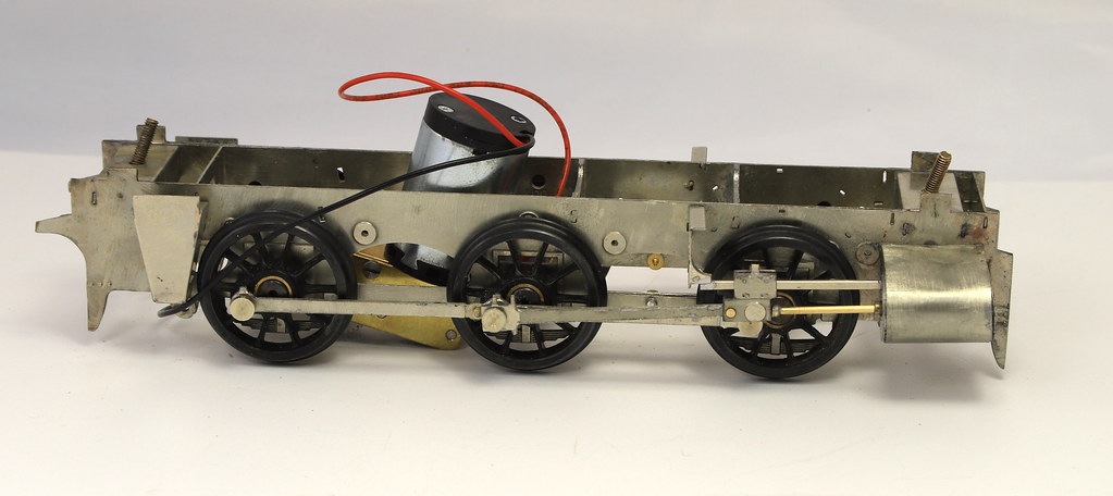
Last weekend I managed to get the basic chassis together with the compensation beams.
One thing to note if anyone comes to build one of these, is that all the spring layers go on the outside of the frames or they interfere with the compensation beams. Needless to say, I had forgotten this from when I did mine and the instructions are a bit vague in this area. Which meant that after making a really neat job of fitting them both sides, I ended up taking them off the back and adding them to the front.
The kit comes with one of the frame spacers in the form of a motor mount which I made use of in my original build but I left out because Brian (Wainwright) whom I am building it for, has supplied an ABC motor gearbox. It does mean that I will have to do something about the holes in the frames though.
- Robpulham
- LNER A4 4-6-2 'Streak'
- Posts: 1721
- Joined: Thu Mar 27, 2008 9:54 pm
- Location: Lower Wensleydale
- Contact:
Re: Great Central Railway Class 5A - LNER J63
Another good session at the bench on Saturday saw the wheels blackened and the Derek Mundy crankpins installed. I have to confess that I am not keen on them. I am not that comfortable with drilling such big holes in the Slaters wheels with the resulting chances of something going wrong.
I enlarged the holes with the pillar drill and I also used the pillar drill to push home the crank pins to keep them vertical and despite that one of them wasn’t in square and needed a little tweak.
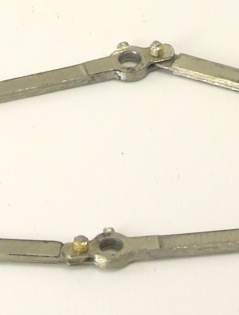
Next up was the coupling and connecting rods, there is a diagram in the instructions on how to cut the coupling rod layers to allow them to articulate on the crankpin. Not knowing any better or having enough confidence to do it any differently that’s how I did mine. Sometime later, Steph Dale went to some trouble to post on Western Thunder a “how to” on cutting the rods to show me how to make them articulate as they should.
Having stored this up for a rainy day I adjusted the cuts and made use of a couple of the spare part rods supplied to make them articulate behind the middle crank pin as they do on the prototype.
There is an etched hole in the outer layer (presumably for a dummy pin) I used this to mark up where to drill the rear layer 6mm. Once all the layers were soldered together and cleaned up, I tapped the hole in the back layer 14ba. Then I threaded some .9mm nickel rod 14ba and made a nut from tube files to a hexagon. Once soldered to the threaded rod I was able to use a 16ba nut spinner to tighten it in to the rods making a nice neat articulated joint.
- Robpulham
- LNER A4 4-6-2 'Streak'
- Posts: 1721
- Joined: Thu Mar 27, 2008 9:54 pm
- Location: Lower Wensleydale
- Contact:
Re: Great Central Railway Class 5A - LNER J63
Next up was looking on the etches for all the bits for the cylinders and it was at this point that I discovered a couple more frame spacers that aren’t mentioned in the instructions. Thankfully they are quite easy to spring into place having trimmed the tabs shorter. As I was doing the first one I recalled having to do the same exercise when I built mine (and that was despite having Mike Cole’s build notes which seem to have been lost In the house move). What was more puzzling was where each one was supposed to fit within the frames.
Thankfully all I had to do was look under mine to refresh my memory.
I have highlighted the two in question in the photo below.
The one at the rear is mentioned in the instructions and it needs the hole for the brake cylinder to be to the left as you look towards the front of the loco.
In the apologies section in the instructions Garth apologises for there being no brake cylinder included. Having knocked one up from tube/rod etc. it seems that the reason for omitting it is that it interferes with fitting one of the plunger pick ups (and oddly the spacer had the hole for locating the cylinder in a vertical spacer which necessitated fitting a locating spigot in the side of the cylinder. I would have thought it much simpler to have made the frame space deeper with a fold line that would allow the cylinder to be fixed from the top. I am sure there was a reason why it was designed like that but we will never know what it was.
I consulted with Brian as to whether to add a wiper pickup instead of a plunger for this wheel and his view was that having gone to the effort of making the cylinder it would be a shame not to use it so a wiper it is.
Having sorted the frame spacers and the brake cylinder I moved onto the sandboxes and the cylinders themselves making reasonable progress. All in all a good weekend’s effort.
- Robpulham
- LNER A4 4-6-2 'Streak'
- Posts: 1721
- Joined: Thu Mar 27, 2008 9:54 pm
- Location: Lower Wensleydale
- Contact:
Re: Great Central Railway Class 5A - LNER J63
What a difference a day makes (or was it the night off and a bottle of cider?)
Yesterday afternoon I scoured the etches to gather up the 18 parts required to make the two crossheads. As always one of them was quite elusive and took a couple of searches before I found it.
After a little bit of testing to ensure I had them in the correct orientation they were soldered up. They are a very clever design and they were both done in just over an hour without any of the stress of fitting the splasher tops to the J6.
Following on from this I added the piston rods using some brass tapered clock pins that I bought a while ago. I then assembled the crossheads onto the slide bars and attached them to the motion brackets.
This was followed by the cylinder wrappers and then after cutting short the crank pins I assembled the chassis with the coupling and connecting rods with a view to giving it a test run.
Sadly, this is as far as I got because the Derek Mundy crankpins are so big on the front axle that they won’t clear the crossheads. Although the screw in caps are a reasonable thickness, I don’t think there will be enough meat in them to create the clearance just by filing them down. At the minute I am pondering what options I have that don’t involve taking the crankpin back out of the wheels. My concern with removing them is getting them back in square without wrecking the wheels.
- Robpulham
- LNER A4 4-6-2 'Streak'
- Posts: 1721
- Joined: Thu Mar 27, 2008 9:54 pm
- Location: Lower Wensleydale
- Contact:
Re: Great Central Railway Class 5A - LNER J63
I managed to sort the crank pins and get clearance. I removed the short 10 ba screw from the rear of the Mundy crank pins on the front axle and then cut the pin back to the boss.
I then filed the boss back to approx half thickness and fitted a long 10ba screw through to become the crankpin. A tapped Slaters crank pin now acts as the retainer allowing clearance for the cross heads. I ended up doing a similar but not quite the same exercise on the middle axles in order to get it to run smoothly.
It's runnning in on the rolling road as I type.
https://youtu.be/QDBUtobGelE
- Robpulham
- LNER A4 4-6-2 'Streak'
- Posts: 1721
- Joined: Thu Mar 27, 2008 9:54 pm
- Location: Lower Wensleydale
- Contact:
Re: Great Central Railway Class 5A - LNER J63
I didn’t have much in the way of modelling time this weekend but I managed to make some progress.
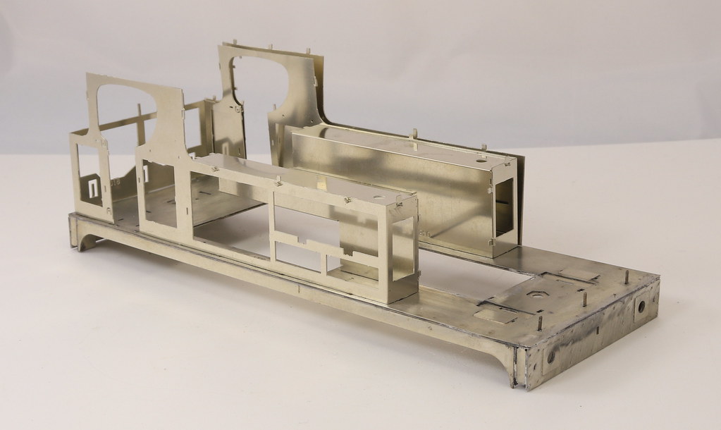
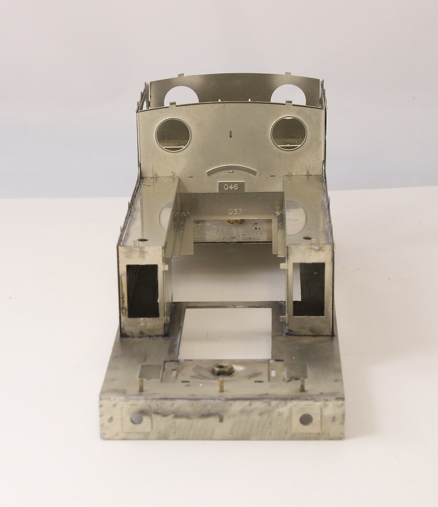
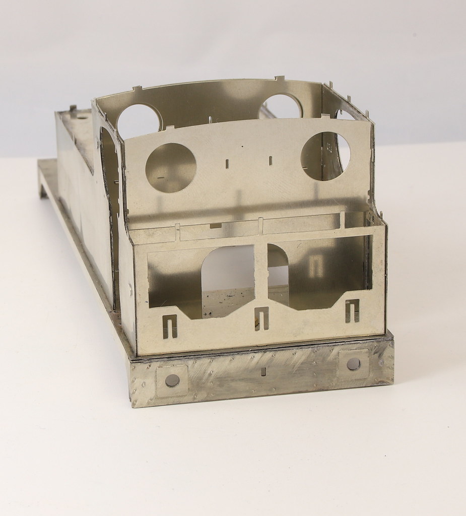
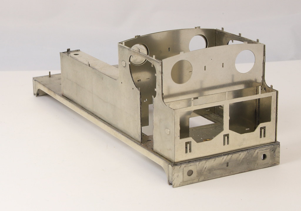
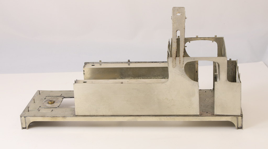
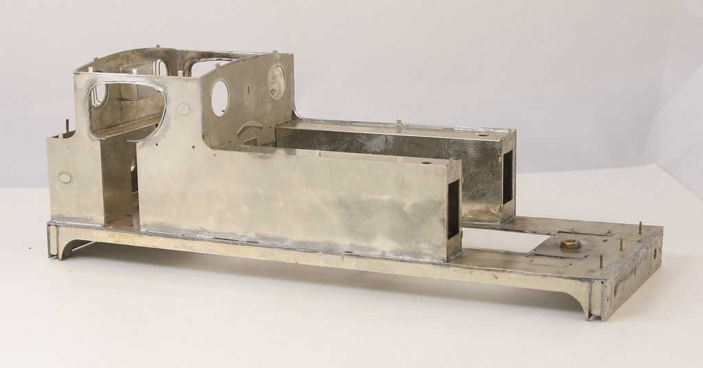
I had cut out the footplate and valances last weekend so they were quickly put together via the tabs. The buffer beams were easily laminated and then again attached via tabs. There are four fold ups that represent the ends of the timber backing to the buffer planks these sit in a recess made up from some strengthening plates (parts 89 and 90) Parts 89 are dotted about the etch so took a bit of tracking down. Parts 90 are shown to be quite close together on the plan of the etches but despite spending the best part of an hour looking I could only find two of the four so I cut some replacements from scrap etch and cut one of the tabs off a couple of the part 89’s
With all the parts found or made it was a simple job to solder it all up to make solid footplate. Then comes the task of chopping all the bits out of the inner cab/tanks/bunker and attaching it to the footplate.
You need to read the instructions thoroughly at this point because if you twist all the tabs you cannot get the overlay to sit in the tab holes. You also need to fit the inner tanks before fitting the overlay because you need to file off all the twisted tabs to get the overlay flat – you will note that in my photo the overlay is still loose as I haven’t filed off the tabs yet.
Talking of tabs, there is much mention of tabs in the instructions at this point. The cab beading has slots for tabs You will note that to make life a bit easier when fitting them I removed the tabs from the door opening on the inner etch but left them on the overlay. This was a trick I learned from the last build.
-
- LNER Thompson L1 2-6-4T
- Posts: 83
- Joined: Mon Jun 18, 2018 11:21 pm
Re: Great Central Railway Class 5A - LNER J63
I have to say I consider myself a modeller until I look at your threads. The skill required to put together something like this is beyond a great many of us and I simply enjoy watching and reading in awe. You had me from remaking the backplate onwards and I had to read the entire thread from there on!!
Thank you for taking the time to share these things with us.
-
- LNER V2 2-6-2 'Green Arrow'
- Posts: 1101
- Joined: Mon Sep 19, 2011 12:24 am
Re: Great Central Railway Class 5A - LNER J63
I look at what Rob does with and feel that anyone who gets intimidated does not want to improve.
The whole thing about modelling is that the more you do, the better you get, and the more you learn.
You cannot use all his techniques in 4 mm modelling, but you can think about things in a different way and
maybe come up with a relevant compromise.
We need people like Rob and indeed Mr King to help us all increase our skills and aims.
Paul
- Robpulham
- LNER A4 4-6-2 'Streak'
- Posts: 1721
- Joined: Thu Mar 27, 2008 9:54 pm
- Location: Lower Wensleydale
- Contact:
Re: Great Central Railway Class 5A - LNER J63
Hi Bunkerbarge,
Although I do appreciate the compliments, I think that you may be doing yourself a disservice in thinking that you are not capable of building one of these to the same standard that I have.
Aside from remaking the backplate which given the cab is enclosed was a bit of indulgence on my part because I like making things and testing myself.
The rest of the kit is one of the easiest to put together that I have built to date. Yes it's got a lot of parts and the instructions could be improved in places.
But everything fits as it should and the accurate tabs and slots mean that it's really difficult to get it out of square. You can also make up large sections without having to solder anything until you are happy with it. In my last photo nothing above the footplate is soldered.
If it makes you feel any better, I have an MOK 8F that I have been building on and off for more than 10 years. The reason it has taken so long is that when I started it, I didn't have the confidence or experience that I have now. So I put it aside until I gained the experience etc.
The key to remember with anything soldered, is that if you get it wrong you can unsolder it, clean up and start again.
The other mantra that I live by is that there are very few right and wrong ways to do things. You will get the best results when using methods that you find most comfortable. When looking at what others do I try to see if what they do will help me within the constraints of what I have to work with.
If I can't see a way of doing that then I discard it or occasionally if I think that buying a piece of equipment or tool will be of benefit then If I can afford it I buy it.
Having said all that, it ultimately depends on what you want from your model making. For me, it is the journey of the build. Once I have built them I tend to do very little with them aside from an occasional run out on test tracks.
However If building a kit is the means to an end because your key passion is running trains or making trackwork or the myriad of other things that make this hobby so enjoyable then you may not have got this far in my rather wordy posting...
- Robpulham
- LNER A4 4-6-2 'Streak'
- Posts: 1721
- Joined: Thu Mar 27, 2008 9:54 pm
- Location: Lower Wensleydale
- Contact:
Re: Great Central Railway Class 5A - LNER J63
This weekend was a one step forward and two back, weekend. I added the sides and fitted the coal bars to the rear cab side sheet and also dry fitted the cab front and inner cab rear.
Where it took a step backwards was on one side, I wasn’t sure that the middle of the tank side had soldered properly to the inner former so I ran the soldering iron over it. Unfortunately, due to the very thin material of the overlay (0.1mm) it left an indentation where I had run the iron.
After consulting with Brian, I removed the side and attempted to remove the indentation but as I suspected it wasn’t possible so I will use the side as a template to make a replacement side from nickel sheet.
- Robpulham
- LNER A4 4-6-2 'Streak'
- Posts: 1721
- Joined: Thu Mar 27, 2008 9:54 pm
- Location: Lower Wensleydale
- Contact:
Re: Great Central Railway Class 5A - LNER J63
Today’s model making session saw the replacement side created. I still need to solder it in place but I am going to fit a few other bits first. It would have been much extra work to add all the tabs so it will need a little more care to fit some parts in place without the help of the tabs but most kits don’t have tabs on these particular parts so it should present too much of a problem.
- Robpulham
- LNER A4 4-6-2 'Streak'
- Posts: 1721
- Joined: Thu Mar 27, 2008 9:54 pm
- Location: Lower Wensleydale
- Contact:
Re: Great Central Railway Class 5A - LNER J63
I am pleased to say that the replacement side has been a complete success and even in bare metal, if you didn’t know I doubt that you could tell that it wasn’t original.
Each side has a couple of ovals representing works plates so I used some off cuts to file up a couple of replacements and soldered them in place before fitting the side. I took measurements of the side that I had taken off to get the correct placement.
Before finally soldering the new side on I fitted the front and rear of the cab and the cupboard on the cab and their overlays.
Once they were all in place, I added the beading around the cab opening. Although I am sure that I used them last time I failed miserably to get the beading to slot onto the tabs in the cab openings. In the end, I filed them off and did it as I would have if there had been no tabs. Using the opening as a former I pre-bent the beading to shape and them with the aid of self-locking tweezers soldered them in place. I will have to revisit one of them as while taking photos this morning I noted a couple of small gaps that need filling.