Gladiator LNER/BR J6
Moderators: 52D, Tom F, Rlangham, Atlantic 3279, Blink Bonny, Saint Johnstoun, richard
- Robpulham
- LNER A4 4-6-2 'Streak'
- Posts: 1721
- Joined: Thu Mar 27, 2008 9:54 pm
- Location: Lower Wensleydale
- Contact:
Re: Gladiator LNER/BR J6
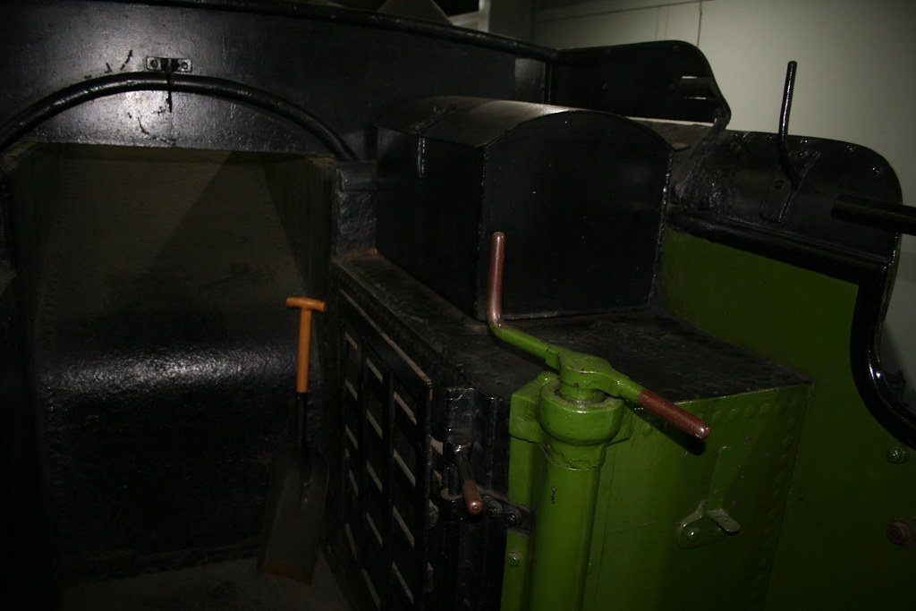
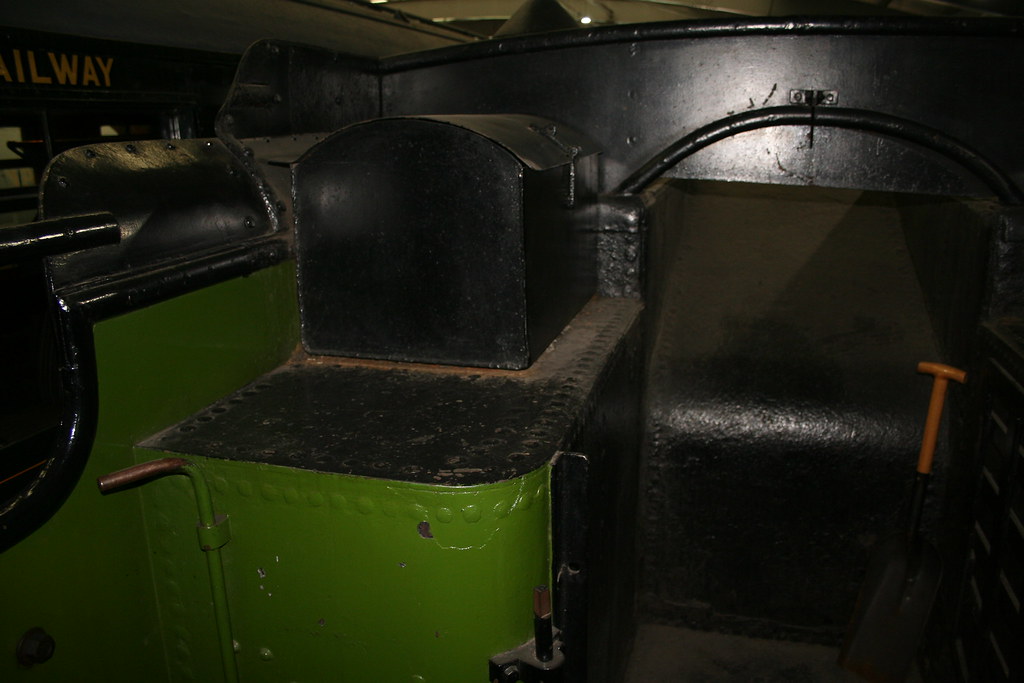
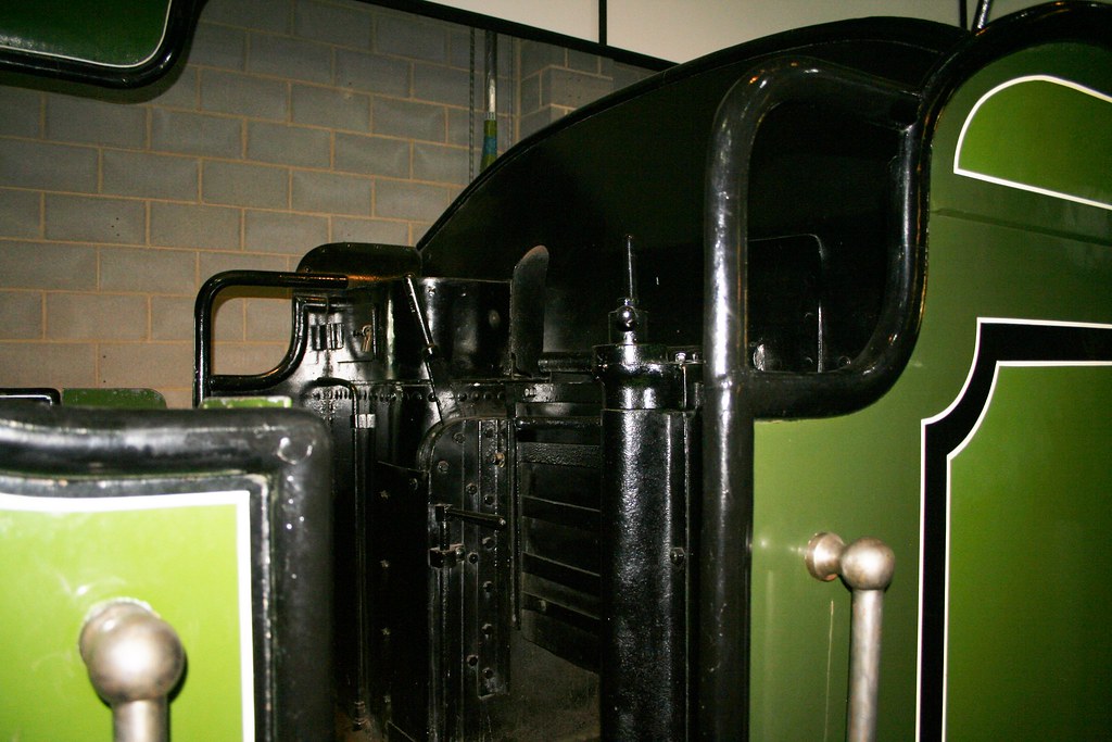
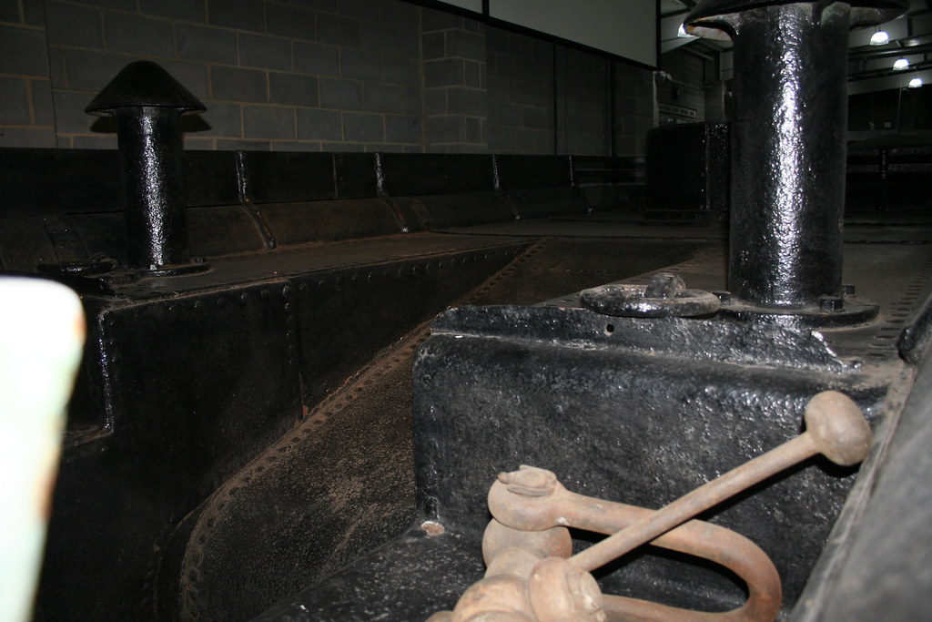
The plot thickens. It seems that there are two externally visibly the same tenders which may well be the 3000 gallon version and the 3500 gallon versions.
By extreme good fortune this year I have taken photos of both. I had forgotten the other until today though.
The first one is located at Shildon, attached to the C1 large-boilered Atlantic and, as proposed in a recent post, I asked one of the museum assistants if I could be accompanied aboard to take photos of the tender top on Saturday and he obliged.
The other is attached by coincidence to the small-boilered Atlantic Henry Oakley whom I encountered at York earlier in the year. Although not great and I didn't get aboard, I did get enough details from my photos to work out which version I need for the J6 and more importantly that the coal space on the kit isn't quite like the two preserved examples each of which are similar but different.
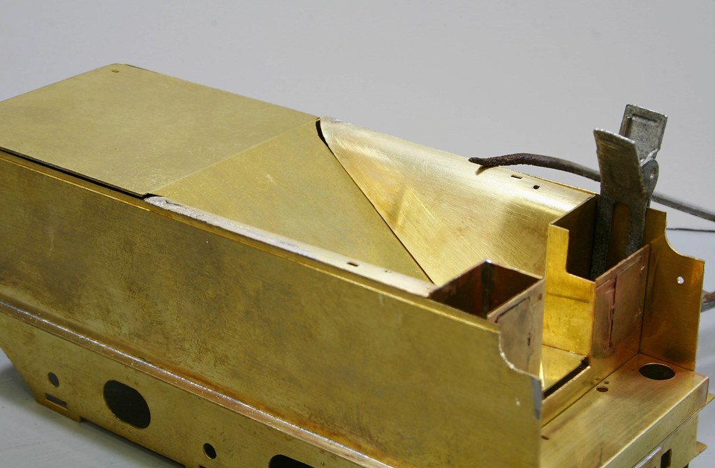
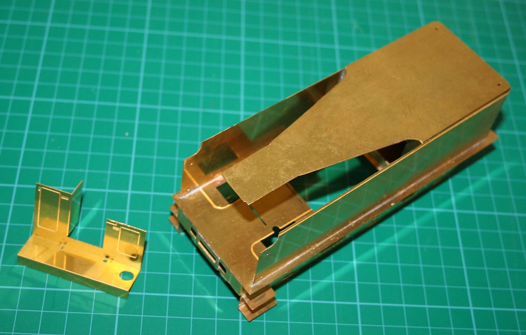
Firstly what the kit looks like:
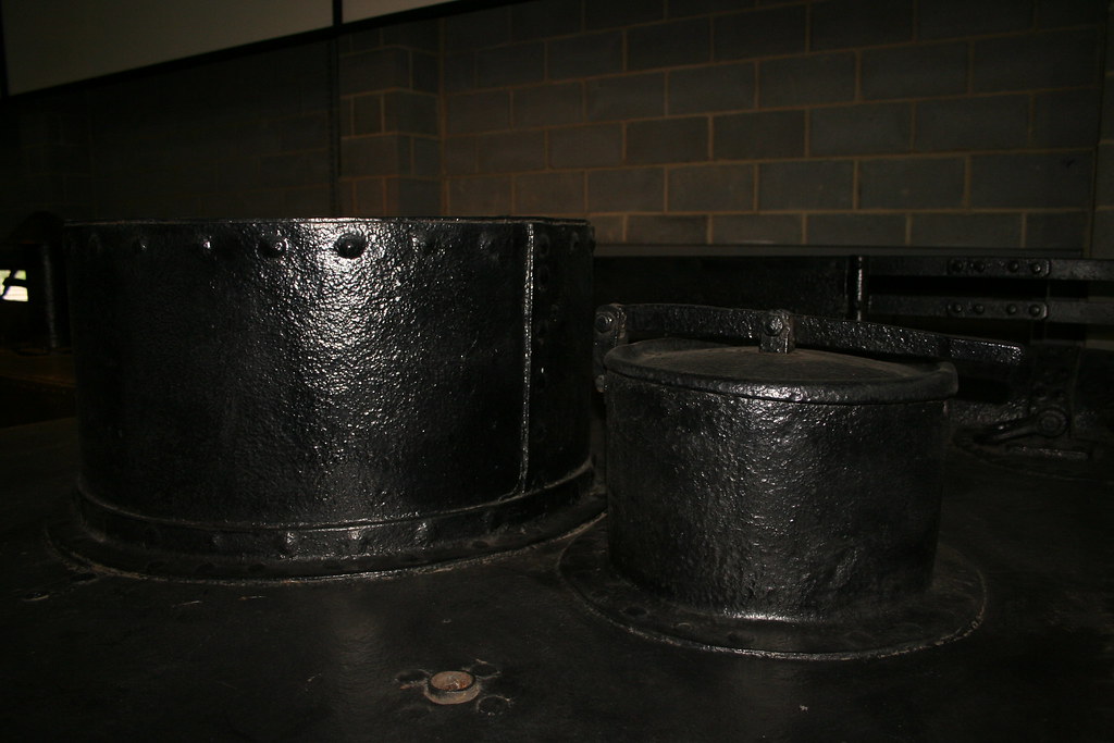
Next the tender attached to the Large Atlantic
I have more detailed photos of the tender top on my Flickr site but these will suffice to tell the story to date.
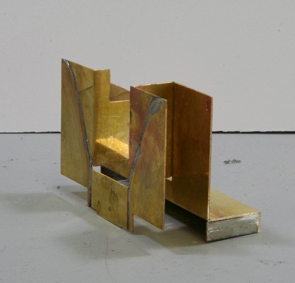
Lastly the tender attached to Henry Oakley and the one which I believe that I need for the J6 when compared to the couple of photos I have of the prototype – no 64206 and more importantly the type that I believe the kit is meant to represent (unless there was a third type which looked externally the same.
As I said, not the best photos but they do show that one side is higher than the other and there is a representation of lockers albeit the prototype show a small door on the higher side whereas the etch has a full height door. The key difference though is in the coal space. Both types of tender have a parallel rather plain functional coal space and I would be surprised if there was a third type that had one with the sloping sides that are inferred by the etches. I think that Malcolm Crawley got it wrong when he designed the tender kit but I would be happy to be corrected in that assumption.
Unless some evidence comes to the fore fairly soon to tell me that I am wrong I intend to modify the coal space to be more like that of the tender attached to Henry Oakely.
By extreme good fortune this year I have taken photos of both. I had forgotten the other until today though.
The first one is located at Shildon, attached to the C1 large-boilered Atlantic and, as proposed in a recent post, I asked one of the museum assistants if I could be accompanied aboard to take photos of the tender top on Saturday and he obliged.
The other is attached by coincidence to the small-boilered Atlantic Henry Oakley whom I encountered at York earlier in the year. Although not great and I didn't get aboard, I did get enough details from my photos to work out which version I need for the J6 and more importantly that the coal space on the kit isn't quite like the two preserved examples each of which are similar but different.
Firstly what the kit looks like:
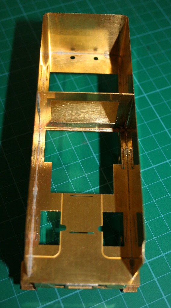
Next the tender attached to the Large Atlantic
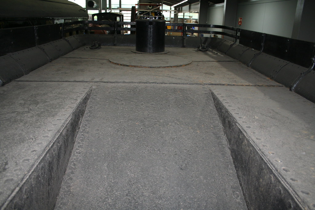
I have more detailed photos of the tender top on my Flickr site but these will suffice to tell the story to date.
Lastly the tender attached to Henry Oakley and the one which I believe that I need for the J6 when compared to the couple of photos I have of the prototype – no 64206 and more importantly the type that I believe the kit is meant to represent (unless there was a third type which looked externally the same.
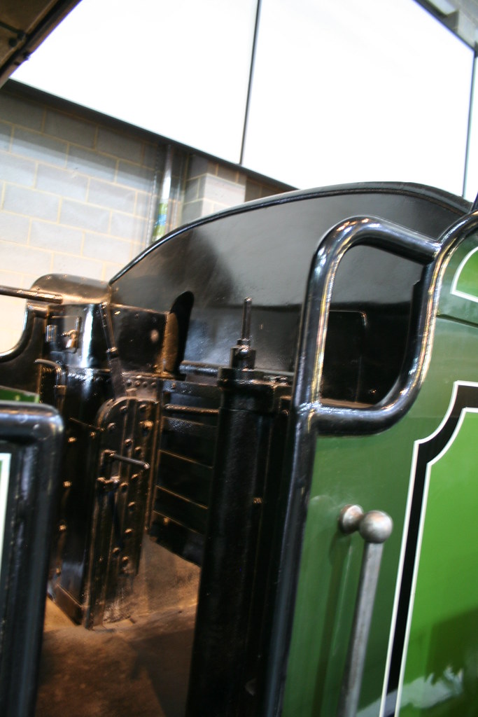
As I said, not the best photos but they do show that one side is higher than the other and there is a representation of lockers albeit the prototype show a small door on the higher side whereas the etch has a full height door. The key difference though is in the coal space. Both types of tender have a parallel rather plain functional coal space and I would be surprised if there was a third type that had one with the sloping sides that are inferred by the etches. I think that Malcolm Crawley got it wrong when he designed the tender kit but I would be happy to be corrected in that assumption.
Unless some evidence comes to the fore fairly soon to tell me that I am wrong I intend to modify the coal space to be more like that of the tender attached to Henry Oakely.
-
- LNER V2 2-6-2 'Green Arrow'
- Posts: 1101
- Joined: Mon Sep 19, 2011 12:24 am
Re: Gladiator LNER/BR J6
Rob, as usual your attention to detail is evident in the photos, however, I must point out that as Malcolm said, neither of these two tenders are
typical of those normally on the Atlantics of either size. The tenders were known as front enders, and had you thought to ask, or indeed
had I thought to remind you, you could have photographed the brake gear, then you would discover that the shoes are on the front of the
wheels, whereas for almost all 6 wheel GNR tenders, they were in fact on the rear edge of the wheel.
I will try and get the build data out later, T.O etc. to provide the data. However it is certain that at least some tenders had the so called
self trimming style interior with sloping sides. Will see if I can reference them again.
When Malcolm designed the three kits, originally for George Norton, he took the view that on a number of Ivatt and Gresley style GN tenders
the differences in details were so slight that it was not cost effective in terms of potential sales, to create tenders that most people could
not see the details of.
For instance some wheelbases are overall the same, but .5 mm difference between the centre wheels, is really difficult to see, and notice.
Indeed as we know many people on this forum are quite happy to accept such discrepancies.
Certainly based on the works drawings, and I know about them often not reflecting real life, both Dias R 43 and R57 have the sloping
shoulders that are represented in the kit.
Paul
- Robpulham
- LNER A4 4-6-2 'Streak'
- Posts: 1721
- Joined: Thu Mar 27, 2008 9:54 pm
- Location: Lower Wensleydale
- Contact:
Re: Gladiator LNER/BR J6
Thanks Paul,
Your efforts are appreciated. I think that my key problem is that although they are now attached to Atlantics the one that I am focusing on was was attached to a J6 and typically all I can make out from the prototype image is the vague outline of a locker and the fact that one side is higher than the other. Which rules out the type that is attached to the C1.
- Robpulham
- LNER A4 4-6-2 'Streak'
- Posts: 1721
- Joined: Thu Mar 27, 2008 9:54 pm
- Location: Lower Wensleydale
- Contact:
Re: Gladiator LNER/BR J6
I have received a lot of information and help from a couple of gents via RMweb Dave Lester and our very own Paul Craig (John Coffin).
With Paul's help I had determined that my tender was indeed a self trimming variety and Dave confirmed it by posting exactly the type of tender that was attached to my loco 64206 from 1935 -1960 (tender 614) and with further help from Paul I believe that I have worked out how it fits together too.
This has proven a very interesting side trip into the world of tenders from which I have learned a lot. I must also offer an apology to the late Malcolm Crawley for remotely suggesting that he might have had it wrong....
More progress to come as it happens
- Robpulham
- LNER A4 4-6-2 'Streak'
- Posts: 1721
- Joined: Thu Mar 27, 2008 9:54 pm
- Location: Lower Wensleydale
- Contact:
Re: Gladiator LNER/BR J6
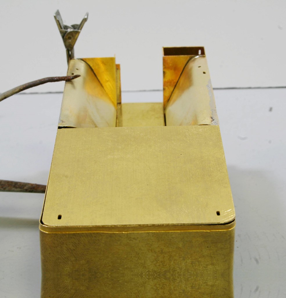
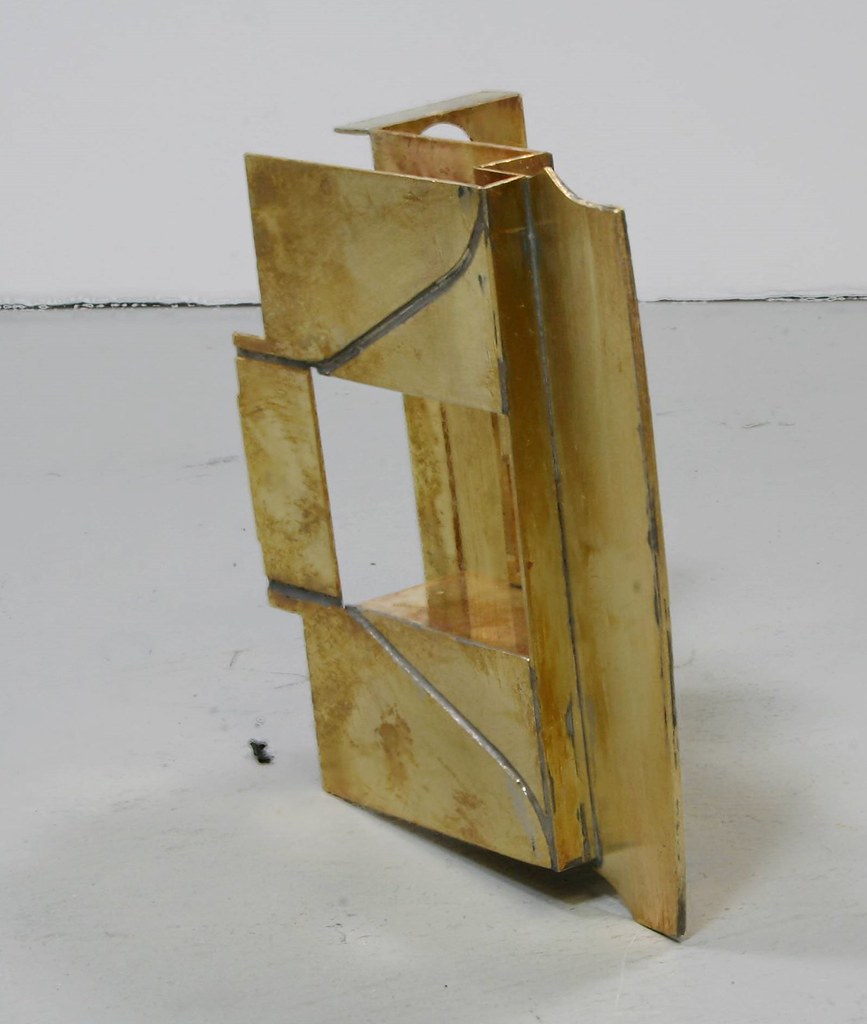
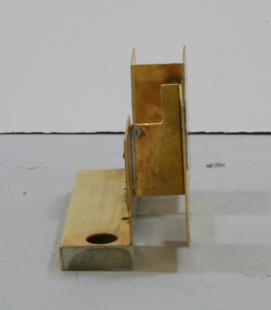
Well, after all the discussion and mental hand wringing by yours truly I do believe that I have cracked it.
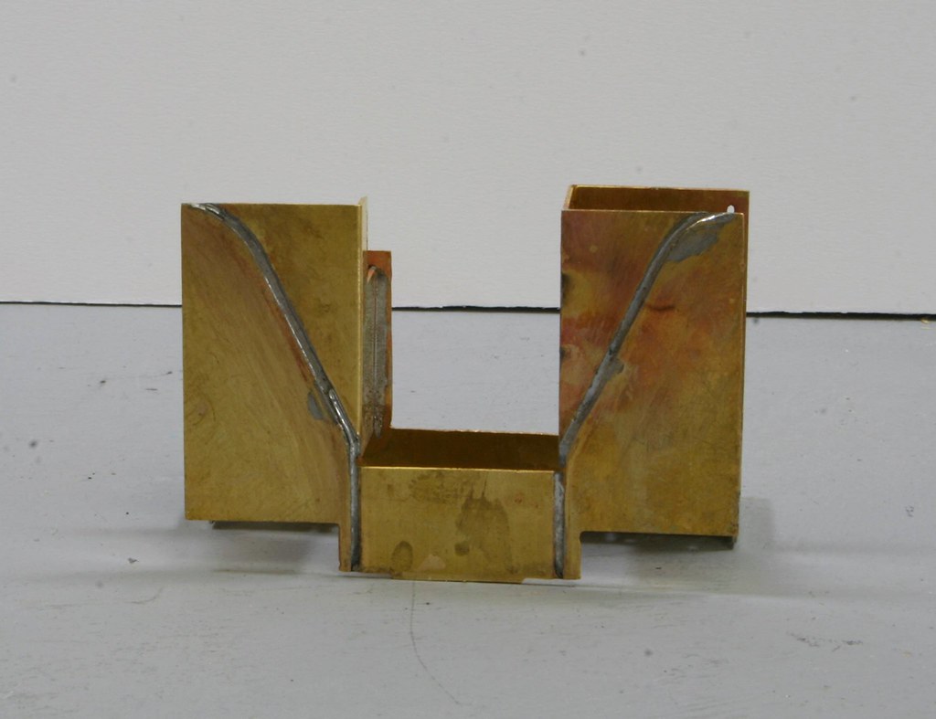
I soldered some scrap etch into each side of the front step of the tender and sods law dictates now that I have I will find suitable parts included (I confess that I didn't even check).
It's all dry fitted at this point and before soldering I do need to check that the tank vents will fit - I may have to straighten the curve a bit to create a flat ledge for the vents to sit on but if I do I will report back.
-
- LNER V2 2-6-2 'Green Arrow'
- Posts: 1101
- Joined: Mon Sep 19, 2011 12:24 am
Re: Gladiator LNER/BR J6
Are you sure about tank vents in BR times. Basically, on GNR, ex GNR locos and tenders, vents weer only there when the tender had
a water scoop functioning.
The placing of them on the Stirling tender no behind No 1 is dubious, although I have seen photos which seem to suggest
something different.
Basically though it looks like you have got it right, but Malcolm always thought putting the flare on first was a better way to
go, although I see very few people do it nowadays.
none the less, looking very good.
Paul
- Robpulham
- LNER A4 4-6-2 'Streak'
- Posts: 1721
- Joined: Thu Mar 27, 2008 9:54 pm
- Location: Lower Wensleydale
- Contact:
Re: Gladiator LNER/BR J6
Hi Paul,
The vents are definitely still there in the 1960 photo and from what I can see between the frames on a second photo that I have there doesn't look to be evidence of a scoop fitted. It would be an easy fix if anyone comes up with a photo to show it fitted.
- Robpulham
- LNER A4 4-6-2 'Streak'
- Posts: 1721
- Joined: Thu Mar 27, 2008 9:54 pm
- Location: Lower Wensleydale
- Contact:
Re: Gladiator LNER/BR J6
Hi Paul,john coffin wrote: ↑Thu Sep 13, 2018 8:12 pm but Malcolm always thought putting the flare on first was a better way to
go, although I see very few people do it nowadays.
I must admit I haven't yet decided on whether to fit the flares before I assemble the innards. Because I use a microflame to solder where I can it's working out which will cause the least amount of cleaning up.
-
- LNER V2 2-6-2 'Green Arrow'
- Posts: 1101
- Joined: Mon Sep 19, 2011 12:24 am
Re: Gladiator LNER/BR J6
No Problem Rob,
with all the previous about a dyno car, it is amazing how little proof we have of tender details, much relying on hearsay rather than fact.
To paraphrase Malcolm, most people even engineers thought of tenders only as water trucks with a coal platform on top.
It is likely the only tender that had any consideration to design was that for the A4's.
The thing about the flare, is that it was designed to be soldered on first before the sides were bent and also flared then
but then you have the problems with the corners making sure the "fingers" are finished cleanly.
Paul
- Robpulham
- LNER A4 4-6-2 'Streak'
- Posts: 1721
- Joined: Thu Mar 27, 2008 9:54 pm
- Location: Lower Wensleydale
- Contact:
Re: Gladiator LNER/BR J6
Hi Paul,
Although that might be the preferred method by Malcolm I would have thought having bent the tank sides that having the flares fitted prior to would have made the job much more difficult and would have added a greater risk of damage the the flares and coal rails while bending them.
Having said all that since there was no reference in the instructions to do it in that order I have in the main followed the assembly order suggested in the instructions. Having just read on a little further while typing this, the instructions as is, have you fitting the tank top before doing anything with the flares - they are the last instruction on page 1.
PS there were parts for the step infills I found them last night attached to the flares.....
Last edited by Robpulham on Mon Sep 17, 2018 9:40 am, edited 1 time in total.
- Robpulham
- LNER A4 4-6-2 'Streak'
- Posts: 1721
- Joined: Thu Mar 27, 2008 9:54 pm
- Location: Lower Wensleydale
- Contact:
Re: Gladiator LNER/BR J6
I was short of time last night so along with finding the step infill pieces, I only managed to assemble the front coal plate and buffer beam.
-
- LNER V2 2-6-2 'Green Arrow'
- Posts: 1101
- Joined: Mon Sep 19, 2011 12:24 am
Re: Gladiator LNER/BR J6
I must confess that it is so long since I
a) read the instructions
and b) wrote them.
I know that Malcolm was always wanting the cab beading to be designed so it fitted a for instance flat cab , because he
felt it much safer when building the item. In particular the beading around the rear of the cab with the cut-outs.
The other thing he belatedly suggested was that the tank should be built onto the solebar before fitting the sideframes.
This was mainly because he felt that it was easier to keep the soleplate flat, I remember building a couple and
finally coming to the same conclusion. It is easier to keep the soleplate flat with another flat object on top,
rather than the complex 3 piece outside frame piece.
Your soldering is definitely a wonder to behold.
Paul
- Robpulham
- LNER A4 4-6-2 'Streak'
- Posts: 1721
- Joined: Thu Mar 27, 2008 9:54 pm
- Location: Lower Wensleydale
- Contact:
Re: Gladiator LNER/BR J6
Thank you.
- Robpulham
- LNER A4 4-6-2 'Streak'
- Posts: 1721
- Joined: Thu Mar 27, 2008 9:54 pm
- Location: Lower Wensleydale
- Contact:
Re: Gladiator LNER/BR J6
Although I haven't posted anything this week things have been progressing albeit slowly.
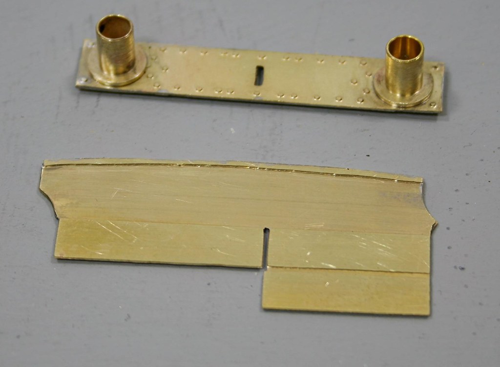
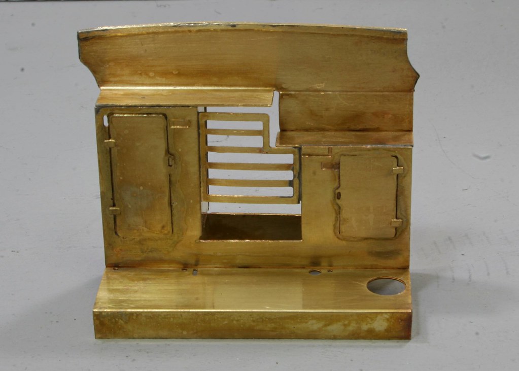
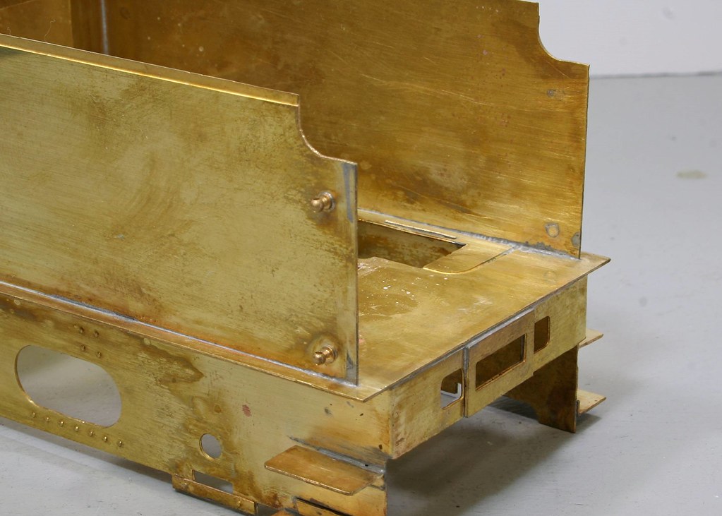
The reason for the slow approach has been a combination of a lot of other things intruding and the fact that I couldn't get my head around how the front coal plate shown in the last post attached to the tender front itself. While I pondered I moved along by fitting hand rail knobs to the tender sides and fitting lifting rings to the coal space sides and tank top/coal chute. I still haven't assembled the innards because I want all the sub assemblies ready and to have an understand of how things fit before committing myself.
Before getting started on anything last night I re-read the instructions and saw the wood for the trees and ended up with this. Still a bit more to do but I am happy with progress.
There is mention in the instructions of a strip 49mm (I think but I don't have the instructions to hand so I will edit the post later and confirm) x 4.5mm
but I couldn't find the part so I used a suitable piece of scrap etch to make the infill piece for the back which forms a shelf behind the coal plate.
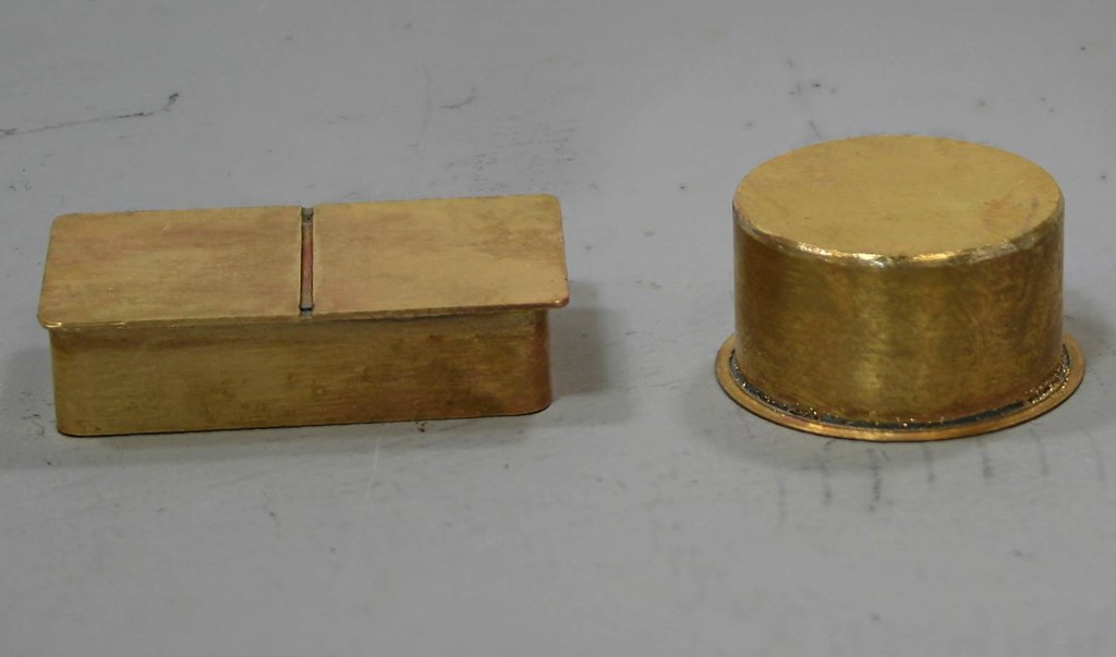
Lastly although not needed for my build but needed for the revision of the instructions I made up the two dome options which are included a rectangular combined dome/filler and the separate dome.
On the round dome everything was a perfect fit whereas on the combined dome I had to take a sliver of the two half etched overlaps to get them to meet squarely a simple exercise that took moments to do with a pair of topiary scissors
- Robpulham
- LNER A4 4-6-2 'Streak'
- Posts: 1721
- Joined: Thu Mar 27, 2008 9:54 pm
- Location: Lower Wensleydale
- Contact:
Re: Gladiator LNER/BR J6
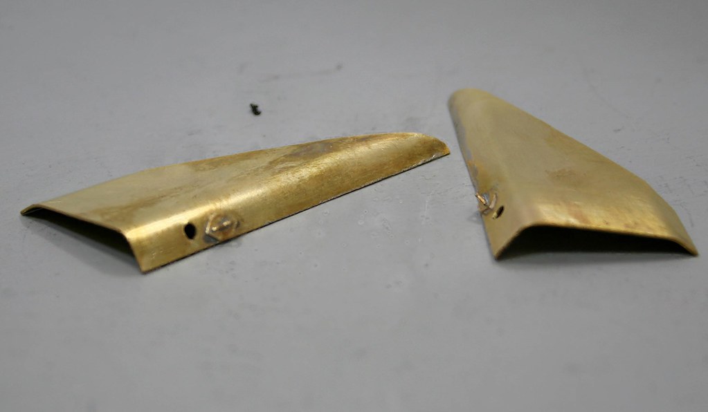
The next job to tackle before starting to assemble everything was the flares and it proved a bit easier than anticipated. Having formed the curves I offered it up the tender and at first I was a little baffled (permanent state of mind at the minute) but quickly realised that I needed to trim the curved end of each side and then it would fit.
I only got part of it soldered on before bed time last night so tonight I will finish that and then take photos.