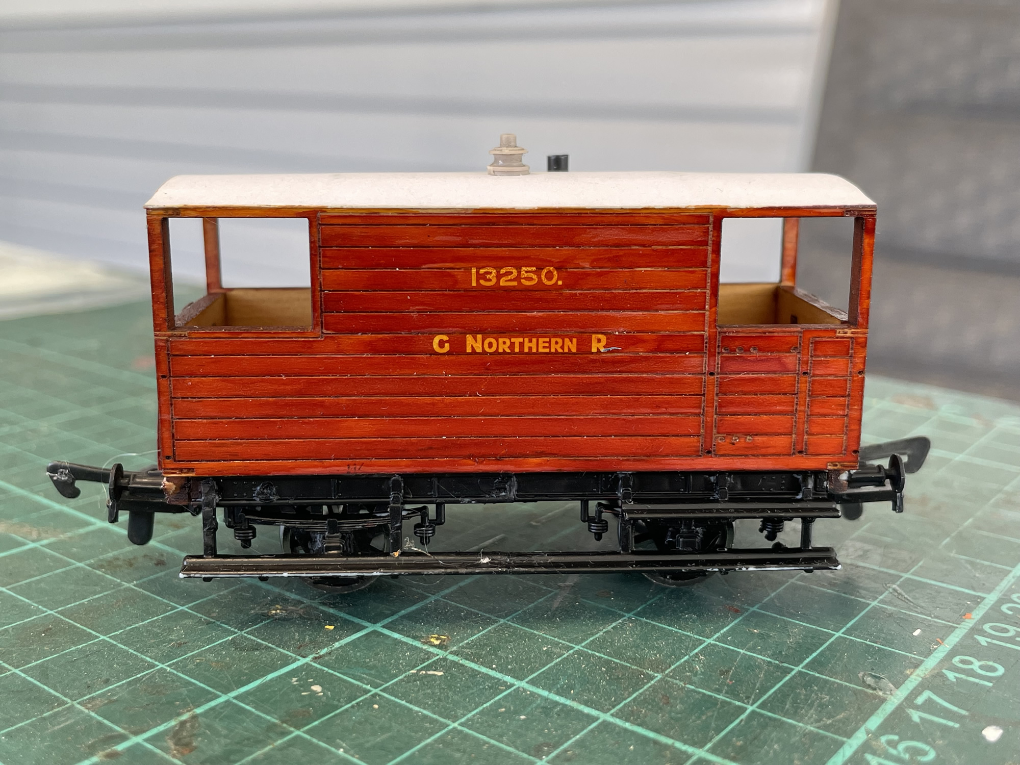
GNR brake van circa 1910
Posted: Tue May 30, 2023 7:03 am
Hello,
I have got to the final stages of a GNR 20 ton brake van build in OO, thanks to "Diagram3D.com" etched timber modelling kit. I purchased 2 of these (horizontal and vertical planked versions W001 and W002) before the vendor provided underfame parts. So anyone buying these kits now will get underframe, axle boxes and running steps in the kit. I have also suggested to the vendor that the instructions need to specify additions of weight to the interior at an early build stage before full enclosure. Sheet lead or lumps of plasticine would be ideal, before the model is enclosed. Of course I learned all this by mistake as usual.
I managed to fabricate an underframe from an Airfix brake van kit, and this gave me the foundation for suitable couplers. UNfortunately, it means that I used a steel underfame which is likely not according to the real van back in the day. And of course the axle boxes and springs are probably not true either. Anyway much of that is hidden under as they say. But there you have it.
Now I am at the stage where I need to add the handrails and I have 0.5mm brass wire for this task.
I am asking those of you who are well versed in this sort of thing how you might go about soldering up said wire into the correct shapes.
The reception holes are already etched into the sides, and I am of a mind to produce a wooden block of the same size as a jig - with holes into which I can locate the bent-to-size wire as a bed for soldering up. I am not sure that cross jointing or butt jointing this size wire for soldering is effective, and thus thinking that I might be better to use silver solder, which I can do.
Using such a block jig brings to mind that the kit vendor should have provided me with a paper template for same, though I suppose I can make my own template with paper and pin.
Any comment or help will be appreciated.
Diagram3D build

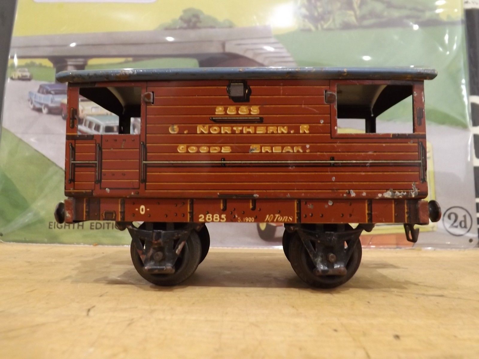
Märklin O gauge example

Real photos

Kimball
I have got to the final stages of a GNR 20 ton brake van build in OO, thanks to "Diagram3D.com" etched timber modelling kit. I purchased 2 of these (horizontal and vertical planked versions W001 and W002) before the vendor provided underfame parts. So anyone buying these kits now will get underframe, axle boxes and running steps in the kit. I have also suggested to the vendor that the instructions need to specify additions of weight to the interior at an early build stage before full enclosure. Sheet lead or lumps of plasticine would be ideal, before the model is enclosed. Of course I learned all this by mistake as usual.
I managed to fabricate an underframe from an Airfix brake van kit, and this gave me the foundation for suitable couplers. UNfortunately, it means that I used a steel underfame which is likely not according to the real van back in the day. And of course the axle boxes and springs are probably not true either. Anyway much of that is hidden under as they say. But there you have it.
Now I am at the stage where I need to add the handrails and I have 0.5mm brass wire for this task.
I am asking those of you who are well versed in this sort of thing how you might go about soldering up said wire into the correct shapes.
The reception holes are already etched into the sides, and I am of a mind to produce a wooden block of the same size as a jig - with holes into which I can locate the bent-to-size wire as a bed for soldering up. I am not sure that cross jointing or butt jointing this size wire for soldering is effective, and thus thinking that I might be better to use silver solder, which I can do.
Using such a block jig brings to mind that the kit vendor should have provided me with a paper template for same, though I suppose I can make my own template with paper and pin.
Any comment or help will be appreciated.
Diagram3D build

Märklin O gauge example

Real photos

Kimball